Series TSTM-DC Test Stands
User’s Guide
6
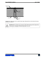
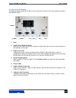
2.4 Installing an Indicator with torque sensor
1. Once the test stand is in a stable and secure position, install an indicator via four thumb screws.
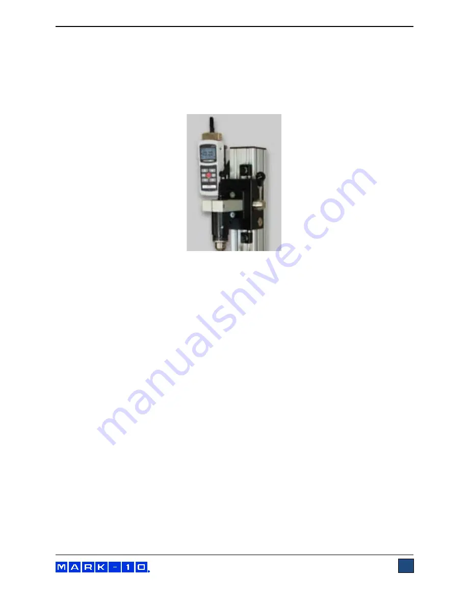
2. Install a torque sensor onto the slider bracket using the supplied hardware, and insert the Plug &
Test connector into the indicator, as shown in the image below:
2.5 Installing the 09-1162 interface cable
If using test stand functions requiring communication between the torque sensor / indicator and test
stand, such as data output, overload protection, etc., connect the interface cable between the
instrument’s connector and the indicator cable connector on the rear of the control panel. This cable may
be used with an M5I or M7I indicator.
2.6 Safety / proper usage
Typical materials able to be tested include manufactured items such as springs, metals, plastics,
electronic components, mechanical assemblies, packaging materials, and many others. Items that should
not be tested include potentially flammable substances or products, items that can shatter in an unsafe
manner, and any other components that can present an exceedingly hazardous situation when acted
upon by torque.
When using a grip, ensure that it secures the sample in such a way that it is prevented from slipping out
during a test, preventing a potential safety risk to the operator and others in the vicinity. If using a grip or
fixture from a supplier other than Mark-10, ensure that it is constructed of suitably rugged materials and
components.
2.7 Connecting power
Plug one end of the power cord into its receptacle at the rear of the control panel and the other end into a
wall outlet with local earth ground (3-prong connector).
Before turning on power, the following safety checks and procedures should be performed:
1. Never operate the test stand if there is any visible damage to the power cord or the test stand
itself. The test stand is powered by 110V/220V. Any contact with this high voltage can cause
serious injury or even death.
2. Ensure that the test stand is kept away from water or any electrically conductive liquids at all
times.
3. Make sure the electrical outlet powering the test stand has local earth ground (3-prong
connector).
Summary of Contents for TSTM-DC
Page 1: ...Series TSTM DC Motorized Torque Test Stands User s Guide...
Page 23: ...Series TSTM DC Test Stands User s Guide 23 10 DIMENSIONS in mm TSTM DC...
Page 24: ...Series TSTM DC Test Stands User s Guide 24 TSTMH DC CONTROL PANEL...
Page 25: ...Series TSTM DC Test Stands User s Guide 25 NOTES...

