background image

Model WT3-200 Wire Terminal Pull Tester 


User’s Guide 


25

13.5 Initial settings  

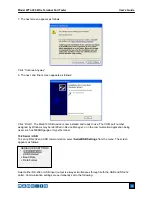
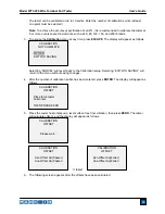
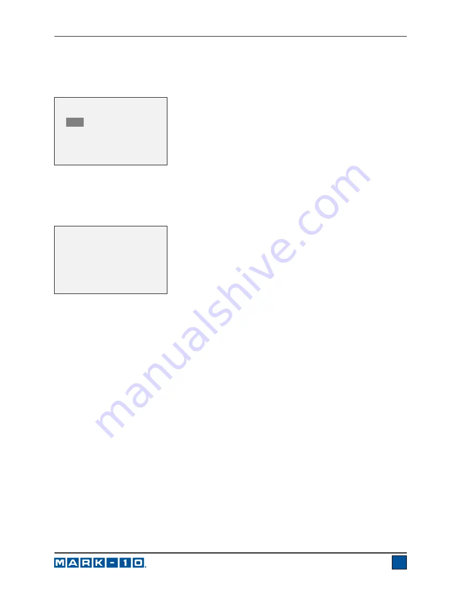
This section is used to configure the initial settings upon powering on the tester. The initial units of 
measurement and the primary reading measurement mode may be configured. To access these settings, 
select 

Initial Settings

 from the menu. The screen will appear as follows: 


The default values are lbF and Real Time. 
 

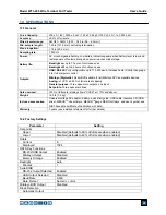
13.6 Information / Welcome Screen 

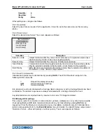
The following screen is displayed at power up and can be accessed at any time by selecting 

Information


from the menu: 


Wire Terminal Tester 

Series WT3 

Model No: WT3-200 
Serial No: 1234567 
Version: 1.0 
(c) Mark-10 Corp. 

INITIAL SETTINGS 


Units 

      lbF 
   Mode 
      Real Time 

Summary of Contents for WT3-200

Page 1: ...Model WT3 200 WIRE TERMINAL PULL TESTER User s Guide...

Page 2: ...vides setup safety and operation instructions Dimensions and specifications are also provided For additional information or answers to your questions please do not hesitate to contact us Our technical...

Page 3: ...d during operation 1 Never operate the tester if there is any visible damage to the AC adapter or the tester itself 2 Ensure that the tester is kept away from water or any other electrically conductiv...

Page 4: ...in a five step process 1 When battery life is greater than 75 the following indicator is present 2 When battery life is between 50 and 75 the following indicator is present 3 When battery life is betw...

Page 5: ...inal fixture or optional ring terminal fixture as shown in the figures below Index the fixtures until the desired slot or ring size is aligned with the cam mechanism adjacent to the lever The fixtures...

Page 6: ...avel The cams will open and the wire will be released 3 4 Installing the ring terminal fixture To install or uninstall the standard terminal fixture or optional ring terminal fixture loosen the screw...

Page 7: ...force N Newton kN Kilonewton 5 Load bar Analog indicator to help identify when an overload condition is imminent The bar increases from left to right indicating increasing load If set points are enab...

Page 8: ...DATA Stores a value to memory transmits the current reading to an external device and or initiates automatic data output depending on setup DELETE Enables and disables Delete mode while viewing stored...

Page 9: ...ic zero and or automatic data storage upon sample break as configured in the Break Detection menu This mode will only appear if enabled in the Break Detection menu 6 CHANGING THE UNITS The WT3 200 can...

Page 10: ...of the instrument and the primary reading is compared to these limits The results of the comparisons are indicated through the three outputs provided on the 15 pin connector thus providing under in ra...

Page 11: ...ntly in memory To enable memory storage select DATA Key from the menu then scroll to Memory Storage and press ENTER Then exit the menu In the home screen the data record number 0000 will appear below...

Page 12: ...s 9 4 Output Statistics Press ENTER to output statistics to an external device The display will show SENDING STATS then STATS SENT If there was a problem with communication the display will show STATS...

Page 13: ...ysically connecting the tester to the PC with a USB cable 1 Insert the Resource CD supplied with the tester into the CD DVD drive in the computer Then navigate in Windows Explorer or My Computer to on...

Page 14: ...into a USB port the driver will automatically be found When the driver installation is complete a message will appear as follows The MARK 10 USB DEVICE driver is now installed and ready to use Non Win...

Page 15: ...y be identified in Device Manager or in the communication application being used such as MESURgauge or HyperTerminal 10 2 Serial USB To set up RS 232 and USB communication select Serial USB Settings f...

Page 16: ...3 Data Communication Individual data points may be transmitted by pressing DATA The WT3 200 will also respond to the following ASCII commands Request the displayed reading MEM Transmit all stored rea...

Page 17: ...y combination of the above functions may be selected 10 4 1 Break Detection Settings Set up the trigger for auto output and storage and the delay to zero the primary and peak readings The display will...

Page 18: ...tions are available Selection Function when pressing DATA RS232 USB Output Outputs data via the serial and USB ports Mitutoyo Output Outputs data via Mitutoyo Digimatic through the serial port Memory...

Page 19: ...Select Calibration from the menu The display will appear as follows 2 Press DIRECTION to invert the display if desired ENTER to continue The display will appear as follows Pin No Description Input Ou...

Page 20: ...setup Selecting EXIT W O SAVING will return to the menu without saving changes 4 After the number of calibration points has been entered press ENTER The display will appear as follows 5 Place the test...

Page 21: ...lay will appear as follows 9 The display will appear as follows Apply a weight equal to the full scale of the instrument then press ENTER Remove the load leave the fixtures in place then press ZERO 10...

Page 22: ...the display will appear as follows To save the calibration information select SAVE EXIT To exit without saving the data select EXIT W O SAVING 12 Any errors are reported by the following screens Disp...

Page 23: ...crement the value from 0 to 9999 When the desired value has been selected press ENTER then ESC to exit the sub menu 12 2 Menu Key Password If enabled every time the MENU key is selected a password mus...

Page 24: ...thorization code Enter the activation code to disable the password 13 OTHER SETTINGS 13 1 Automatic Shutoff The tester may be configured to automatically power off following a period of inactivity whi...

Page 25: ...f the AC adapter is plugged in the tester will ignore these settings and keep the backlight on Selecting the On or Off setting in the Backlight menu will manually turn the backlight on or off 13 3 LCD...

Page 26: ...be configured To access these settings select Initial Settings from the menu The screen will appear as follows The default values are lbF and Real Time 13 6 Information Welcome Screen The following s...

Page 27: ...e devices Analog 1 VCD 0 25 of full scale at capacity General purpose Three open drain outputs one input Set points Three open drain lines Safe overload 150 of full scale display shows OVER at 110 and...

Page 28: ...ic Storage Disabled Automatic Zero Disabled Break Detection Settings Trigger Threshold 5 Auto Zero Delay 3 sec Automatic Shutoff Enabled Minutes 5 Beeps Keys Enabled Alerts Enabled Set Points Momentar...

Page 29: ...tion to our standard line of products we can provide modifications and custom designs for OEM applications Our engineering team is eager to satisfy any special requirements Please contact us for furth...

Reviews: