background image

3-2

Setup Menu

Mark Levinson

Navigating the Setup Menu (continued)

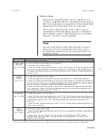
To open the setup menu:

Press and release the front panel or remote control 

setup button

.

When the 

setup menu

is closed, pressing and releasing the

setup button

opens the 

setup menu

on the front panel

display as shown to the left. The front panel 

setup LED

lights

red to indicate that the 

setup menu

is open.

Both the front panel and remote control can be used to navigate
the 

setup menu

structure shown in the illustration on the previous

page. The bulleted items that begin below indicate the commands
the front panel and remote control perform when the 

setup

menu

is open.

setup button

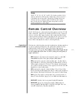
Returns to the previous menu, eventually closing the 

setup

menu

.

Deselects the selected parameter without saving setting
adjustments that have not been previously stored. The

RESTORING

message will appear on the front panel display as

shown to the left to indicate that new adjustments are not
being stored.

enter button

Advances to the next menu.

Selects the current parameter. When a parameter is selected,
the equal sign (=) between the parameter label and the parameter
setting will blink to indicate that setting adjustments can be
made with the 

volume knob

or

volume ± buttons

.

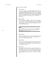
Deselects the selected parameter, saving setting adjustments
that have not been previously stored. The 

SAVING DATA

message will appear on the front panel display as shown to
the left to indicate that new adjustments are being stored.

Note

When a parameter is deselected, the 

NO CHANGE

message

will appear on the front panel display as shown to the left if
no changes have been made to the parameter’s last stored
setting.

No320S Setup

RESTORING

SAVING DATA

NO CHANGE

Summary of Contents for 320S

Page 1: ...Owner s Manual N 320S Preamplifier...

Page 2: ...block air flow through ventilation openings or heat sinks 9 NEVER bypass any fuse 10 NEVER replace any fuse with a value or type that is not specified by the manufacturer 11 NEVER attempt to repair th...

Page 3: ...ALER OR MARK LEVINSON CUSTOMER SUPPORT AT 781 280 0300 OR www marklevinson com FOR ASSISTANCE CHANGES OR MODIFICATIONS MADE TO THIS COMPONENT THAT ARE NOT EXPRESSLY APPROVED BY MARK LEVINSON MIGHT DAM...

Page 4: ...Guide 1 8 Section 2 Basic Operation Front Panel Overview 2 1 Rear Panel Overview 2 5 Linking 2 9 Making Link Connections Constructing Link Communication Cables Creating a Slave Chain Link Controls Rem...

Page 5: ...P Surround Sound Processor Mode 4 8 Section 5 Troubleshooting Maintenance Troubleshooting 5 1 No Power No Remote Control Operation No IR Learning No Main Output No Record Output Audible Hum Missing In...

Page 6: ...to indicate important operation and maintenance instructions included in the accompanying documentation Appears on the component to indicate compliance of with the EMC Electromagnetic Compatibility a...

Page 7: ...mponents the N 320S relies on clean noise free AC power to deliver maximum performance Unfortunately most AC power does not meet these standards Common household appliances such as refrigerators TVs a...

Page 8: ...input signal and ground connection eliminating ground loop noise between the N 320S and the associated component As a result input signals pass through the N 320S with remarkable freedom from interfer...

Page 9: ...tors and complete surround sound processor integration allow it to accommodate a wide range of demands Even more a series of advanced techniques shield audio circuits resulting in an incomparable soun...

Page 10: ...ard Product registration serves no warranty purposes Retain the original dated sales receipt as proof of warranty coverage Installation Considerations The N 320S requires special care during installat...

Page 11: ...short as possible Note In some cases it is better to use longer interconnect cabling between the preamplifier and the power amplifier to allow for shorter loudspeaker wires DO select a dry well ventil...

Page 12: ...TS ARE PROPERLY GROUNDED DO NOT DEFEAT THE SAFETY PURPOSE OF POLARIZED OR GROUNDING TYPE PLUGS WITH GROUND LIFTER OR CHEATER ADAPTORS DOING SO MAY CAUSE DANGEROUS VOLTAGES TO BUILD UP BETWEEN COMPONEN...

Page 13: ...ion at 50Hz in European Union countries Before operating the N 320S make sure the ac mains connector label indicates the correct operating voltage for the current location CAUTION DO NOT ATTEMPT TO AD...

Page 14: ...the initialization sequence The main output connectors are muted while the N 320S performs the initialization sequence Continuous Operation The N 320S should be unplugged during lightning storms and e...

Page 15: ...inst RF interference and other common mode noise 2 Connect the desired N 320S stereo input connectors to the source component e g CD player output connectors Use the N 320S balanced XLR stereo input c...

Page 16: ...anel select knob or press the remote control select buttons to select the N 320S input that corresponds to the N 320S stereo input connectors selected in step 2 The N 320S front panel display indicate...

Page 17: ...nd powers on the N 320S When powered on the N 320S automatically enters standby after completing the initialization sequence When the N 320S is powered on pressing the power button disconnects power f...

Page 18: ...inputs inputs for which the Name parameter has been set to unused 4 front panel display Includes 12 alphanumeric characters that provide one line viewing of information During normal operating mode th...

Page 19: ...Note the following about using the volume knob Rotating the volume knob quickly accelerates the rate of change to accommodate large adjustments Rotating the volume knob too quickly decelerates the ra...

Page 20: ...front panel balance LED remains lit if the left to right channel balance of the main output connectors is offset 12 mute button LED Activates and deactivates mute Pressing and releasing the mute butt...

Page 21: ...indicates the correct operating voltage page 1 7 for the current location continued ac mains main outputs inputs main outputs inputs 1 2 3 4 5 1 6 7 7 6 5 4 3 2 1 2 1 record outputs communication slav...

Page 22: ...er amplifier will offer the highest possible performance with the best protection against RF Interference and other common mode noise 3 stereo main output connectors Provide left and right channel ana...

Page 23: ...including master volume and balance do not affect record output levels 5 slave in communication ports Provide links to compatible Mark Levinson components allowing the N 320S and other linked componen...

Page 24: ...ovides 12 or 5V DC output to control connected components One 3 5mm mini jack labeled trigger output is available for a mono plug Tip Sleeve connection The Trig parameter can be used to configure the...

Page 25: ...essors N 31 and N 31 5 Reference CD Transports N 36 N 36S N 360 and N 360S Digital Audio Processors N 39 and N 390S CD Processors can be used as either digital audio processors or digital transports i...

Page 26: ...processor digital transport or N 320S RJ 45 plugs provide an 8 pin connection Use a 6 pin RJ 11 plug to connect to a power amplifier RJ 11 plugs provide a 6 pin connection in which connector pins 7 an...

Page 27: ...r amplifier s Connect the slave in communication port on the first digital transport to the master communication port on the digital audio processor Digital transports CANNOT be included in a slave ch...

Page 28: ...component A Digital Transport s B Digital Audio Processor C N 320S D Power Amplifier s At this point the front panel standby LEDs on all linked components should be blinking in unison Note Linked com...

Page 29: ...as either a digital audio processor or a digital transport in a slave chain 2 13 N 320S Basic Operation Link Controls Linking Mark Levinson components allows them to share controls such as display int...

Page 30: ...electing analog inputs on the linked N 320S Pressing and releasing the digital transport remote control select button scrolls through all available digital or analog inputs depending on whether the di...

Page 31: ...ems below and to other precautions that appear throughout this user guide The bulleted items that begin below are not applicable when the N 320S is using the rear panel ir input connector DO eliminate...

Page 32: ...rk Levinson standby PREAMPLIFIER N 320S enter setup polarity balance display mono mute volume select 2 3 6 7 8 10 11 9 5 4 1 The numbers in the N 320S remote control illustration shown above correspon...

Page 33: ...The factory default input volume level offset is 0 0dB Whenever an input is selected the N 320S automatically applies the Offset parameter setting to master volume level Note the following about usin...

Page 34: ...e 4 3 for additional information Note When the balance control is closed the front panel balance LED remains lit if the left to right channel balance of the main output connectors is offset 9 display...

Page 35: ...ster volume level attenuation that occurs when mute is activated The mute level can be set in 0 1dB increments between 10 0 and 80 0dB The factory default mute level is 20 0dB Note Pressing the volume...

Page 36: ...T 1 GO INPUT 2 GO INPUT 3 GO INPUT 4 GO INPUT 5 GO INPUT 6 GO INPUT 7 GO MUTE GO UNMUTE GO BALANCE EXIT BALANCE DISPLAY OFF DISPLAY DIM DISPLAY HALF DISPLAY FULL 12v L 5v P 80 0 to 10 0 40 0 to 80 0 N...

Page 37: ...ter without saving setting adjustments that have not been previously stored The RESTORING message will appear on the front panel display as shown to the left to indicate that new adjustments are not b...

Page 38: ...before making adjustments Set Inputs Menu Selecting Set Inputs prompts the selection of the desired input e g Input 1 Selecting an input opens the corresponding Set Inputs menu as shown below which ca...

Page 39: ...stereo input connectors labeled 1 Input 2 is assigned to the stereo input connectors labeled 2 and so on Custom input names should be based on the component with which the input is associated For ins...

Page 40: ...entifies an input associated with a tape deck TAPE Identifies an input associated with the corresponding Mark Levinson component Linked Mark Levinson components must have recognizable custom input nam...

Page 41: ...Name parameter and access the custom names list shown in the top left corner of the previous page The current input name blinks as shown to the left to indicate that a new input name can be selected...

Page 42: ...ls for the selected input which sometimes prevents input sources with low gain levels from producing low signal to noise ratios Decreasing the Gain parameter setting decreases gain levels for the sele...

Page 43: ...RECORD INPUT AND OUTPUT CONNECTORS IT IS RECOMMENDED TO SET THE REC OUT PARAMETER TO NONE TO PREVENT RECORD FEEDBACK LOOPS IN WHICH THE ASSOCIATED COMPONENT ATTEMPTS TO RECORD ITS OWN OUTPUT SIGNALS T...

Page 44: ...UME UP VOLUME DOWN SELECT NEXT SELECT PREV INTENSITY MUTE KEY MONO KEY POLARITY KEY STANDBY KEY ENTER KEY SETUP KEY BALANCE KEY EXIT STANDBY GO STANDBY GO INPUT 1 GO INPUT 2 GO INPUT 3 GO INPUT 4 GO I...

Page 45: ...nds 6 When the desired IR command is selected press the enter button to teach this command to the learning remote control The SENDING message will appear on the front panel display as shown to the lef...

Page 46: ...g the 12v L setting 12v L 5v P configures the trigger output connector to send a 12V level constant signal to the connected component whenever the N 320S is taken out of standby This signal is not pre...

Page 47: ...into standby The front panel standby LED blinks red to indicate that the N 320S is in standby When the N 320S is in standby pressing and releasing the standby button takes the N 320S out of standby Th...

Page 48: ...o cycle through all available SLEEP parameter settings 4 When the desired setting is selected press the front panel or remote control enter button to close the SLEEP parameter Otherwise the SLEEP para...

Page 49: ...easing the polarity button inverts main output signal polarity The front panel polarity LED lights red to indicate that main output signal polarity is inverted When main output signal polarity is inve...

Page 50: ...offset in favor of the right channel Rotate the volume knob counterclockwise or press the volume button to decrease the output level of the right channel The balance control appears as shown to the le...

Page 51: ...g is L R Selecting the L R mono mode sends an equal combination of left and right channel input signals to the left and right channel main output connectors Refer to L R Balance Control Tip next page...

Page 52: ...the front panel display as shown to the left 2 Press and release the mono button to cycle through all available MODE parameter settings until the L R mono mode is selected as shown to the left of step...

Page 53: ...h all available MODE parameter settings until the L R mono mode is selected as shown to the left 3 Press and release the front panel or remote control enter button to close the MODE parameter Otherwis...

Page 54: ...sor interferes with some Dolby noise reduction processing Processors that feature Dolby Pro Logic decoding sometimes also feature a form of Dolby noise reduction similar to the Dolby B noise reduction...

Page 55: ...nput connectors on the N 320S For best performance use balanced XLR connections whenever possible 5 Connect the main output connectors on the N 320S to the appropriate input connectors on the power am...

Page 56: ...t to indicate that a new input name can be selected from the custom names list 9 Rotate the front panel volume knob or press the remote control volume buttons to scroll through all custom input names...

Page 57: ...nt panel display 5 Examine the electrical circuit breaker to ensure that power is supplied to the wall outlet to which the N 320S is connected No Remote Control 1 Eliminate obstructions between the re...

Page 58: ...lume to an inaudible level 5 Make sure the N 320S main output connectors are connected to an operational power amplifier and that the associated power amplifier is connected to operational loudspeaker...

Page 59: ...ments listed in the table on page 2 11 6 Make sure Link controls have been enabled on the linked digital transport s linking menu which allows activation and deactivation of individual Link controls R...

Page 60: ...ings 1 Press and release the front panel power button to power off the N 320S It is also recommended to power off all associated components 2 Press and hold the front panel setup and display intensity...

Page 61: ...cloth to remove dirt and fingerprints from the N 320S exterior surface Do not use a cloth made with steel wool or metal polish If needed this cloth can be dampened with isopropyl alcohol Do not dampe...

Page 62: ...gle ended Mark Levinson RCA stereo main output 2 single ended Mark Levinson RCA stereo record outputs 2 8 pin RJ 45 connectors for Link communication 1 6 pin modular RJ 11 connector for RS 232 communi...

Page 63: ...8V 12dB 3 3V 1 6V 6dB 6 6V 3 3V 0dB 13 2V 6 6V Input Impedance 100k Output Impedance 50 THD N 0 001 Crosstalk 90dB any input to any output input terminated Residual Noise 20Hz to 20kHz input terminat...

Page 64: ...volume mono select power standby PREAMPLIFIER N 320 17 75 450 85mm 13 62 345 95mm 2 07 52 45mm 2 92 74 04mm 2 07 52 45mm 2 66 67 56mm 0 26 6 48mm Top View Specifications are subject to change without...

Page 65: ...Input 5 Input 6 Input 7 Mute MaxVol Trig Sw Mono Playback Balance Intensity Polarity Setup Menu Parameters Control Mode Settings Set Inputs Input 1 Name Gain Offset Rec Out Input 2 Input 3 Input 4 In...

Page 66: ...ist 3 4 3 5 3 6 ill 3 7 CLEAR message 5 4 CLEAR SETUP message 5 4 communication circuits 1 2 1 3 compatibility linking 2 9 2 11 connectors ac mains 1 6 1 7 1 8 2 1 2 2 2 5 2 16 5 1 A 1 balanced 1 2 1...

Page 67: ...320S 1 3 to 1 4 I impedance A 2 infrared signals 2 8 2 16 3 8 3 9 3 10 initialization sequence 1 8 2 1 2 12 4 1 INPUT 1 7 input names 3 5 3 6 input connectors 1 2 1 3 1 9 1 10 2 6 3 4 3 7 3 9 4 9 A 1...

Page 68: ...ng mode 2 1 2 2 2 3 2 15 2 16 SSP mode 1 3 2 3 2 17 3 4 3 5 4 4 4 8 to 4 10 see also surround sound processors mono button 2 2 2 18 3 9 4 5 4 6 4 7 MONO KEY IR command 3 9 mono LED 2 2 2 18 4 5 mono m...

Page 69: ...to 2 16 overview 2 15 to 2 19 ill troubleshooting 5 1 residual noise A 2 RESTORING message 3 2 return authorization IBC RF interference 1 6 1 9 2 6 2 8 4 9 RJ 11 connectors 2 8 2 10 A 1 RJ 45 connect...

Page 70: ...1 to 5 3 TUNER input name 3 5 tuners 3 5 U unpacking N 320S 1 4 to 1 5 unused input name 1 2 1 3 2 2 2 17 3 5 5 3 V VCR input name 3 5 VCRs 3 5 3 8 volume buttons 2 17 2 19 3 2 3 3 3 6 3 9 3 10 4 4 4...

Page 71: ...way to rectify the situation and if needed to obtain return authorization in the event that the product must be returned to the factory for repair Alternatively customers may contact Customer Support...

Page 72: ...ephone 781 280 0300 Fax 781 280 0490 www marklevinson com Customer Support Telephone 781 280 0300 Sales Fax 781 280 0495 Service Fax 781 280 0499 Product Shipments 16 Progress Road Billerica MA 01821...

Reviews: