background image

Summary of Contents for STEAM-IT ST-AG

Page 1: ...SERVICE PARTS MANUAL STEAM IT STYLE F GAS OPERATED COOKER MODELST AG An Employee Owned Company Form Number S2127 Printed in U S A Copyright 1977 35 Garvey Street Everett MA 02149 4403 ...

Page 2: ...3 1 3 3 1 3 3 1 3 3 3 4 3 4 3 4 4 1 4 1 4 1 4 1 4 1 4 1 4 1 4 2 4 2 I SECTION 5 TROUBLE SHOOTING 5 1 General 5 1 5 2 Trouble Shooting Guides 5 5 3 Electrical Fault Isolation 5 1 54 Electrical Trouble Shooting Procedures 5 3 5 4 1 Incoming Power 5 3 5 4 2 Electrical Inspection 5 5 5 4 3 Direct Spark Ignition Control System 5 5 5 4 4 50 Minute Timer 5 7 54 5 Solenoid Gas Valve 5 7 5 4 6 Buzzer 5 7 5...

Page 3: ... Flame Current Meter 5 6 SECTION 6 MAINTENANCE 6 1 Door Spring Disengagement 6 1 6 2 Door Removal 6 2 6 3 Gasket Removal 6 2 6 4 Door Seal Tension Adjustment 6 3 6 5 Air Shutter Adjustment _ 6 5 6 6 Gas Regulator Adjustment 6 5 SECTION 7 ILLUSTRATED PARTS LIST 7 1 Cabinet and Frame Assembly 7 2 7 2 Steam Exhaust Valve Assembly 7 5 7 3 Burner Chassis Subassembly 7 6 7 4 Door Assembly 7 8 7 5 Door L...

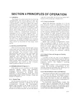
Page 4: ... is perfectly level 1 2 BASIC FUNCTIONING The Model ST AG steam cooker becomes operational when water is loaded into the cooking compartment and the 60 minute timer is set to the desired cooking time With the time set the electric ignition comes on the exhaust valve closes automatically and the burner ignitor is energized The gas is ig nited by the electrodes to heat the water in the cooking cylin...

Page 5: ...ction must be 2 inches from left side 12 inches from right side and 2 inches from back 2 3 GAS CONNECTION The gas connection is made by removing the lower front panel to gain access to the gas supply line elbow Figure 7 3 Index 37 WARNING Gas lines should be thoroughly blown out and cleaned before connection to the Steam It is made This will prevent dirt dust or pipe compound from reaching the sen...

Page 6: ...e to ground unit chassis from ground terminal box to an outside ground S2127 2 5 WATER AND DRAIN CONNECTIONS The Stearn lt cooker design incorporates provisions for manually adding and draining water therefore no external connections for water and drain are required 2 6 INSTALLATION CHECKOUT After the Steam It cooker is completely assembled and properly located with elec trical and gas supply conn...

Page 7: ... to the desired cooking time Observe pressure increase indicated by pressure gauge 23 5 At the close of the preset cooking period the timer pointer will stop at the 0 position on the dial This will shut down the Steam It and automatically open the exhaust valve The Buzzer will continue to sound un til the dial pointer is manually turned to the OFF position 6 Observe that the indicator light Figure...

Page 8: ...e If more water is added to main tain the required level an occasional tablespoon of vinegar may be added as well in order to compensate for new mineral deposits of the fresh water CAUTION A high degree of mineral salts in the water can cause pitting of the cooking compartment unless the above direc tions are followed the cooking com partment thoroughly cleaned and drained each night and the door ...

Page 9: ...round door while pressure is building up door seal adjustment must be made Refer to subsection 6 3 1 for in structions 5 Remove pans and transfer to serving area Perforated pans if they are to be transferred to the serving area should be underlined with solid pans 6 Check that water leveL is at six quart capacity before starting another cook ing cycle If strong flavored foods such as onions or sea...

Page 10: ...ng mild non abraslve solution Rinse and dry thoroughly CAUTION Failure to wash compartment may result in pitting of the aluminum surfaces Use only mild detergent suitable for use with aluminum 4 Replace pan supports in compartment and leave door open 3 3 1 Exhaust Silencer The exhaust silencer Figure 7 1 Index 51 should be removed and cleaned periodically As the cooking compartment is exhausted of...

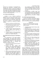
Page 11: ...ollar at the top rear of the Steam lt The air will continue to escape as pressure builds up and the steam trap will close after all the air has been forc ed out of the cooking compartment 4 3 2 Pressure Switch When the pressure reaches 9 to 10 psi the Steam It is set to operate at 15 psi of pressure the contact on low pressure switch Close on Rise will close thereby closing the circuit to the cloc...

Page 12: ......

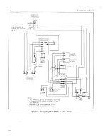
Page 13: ...S SHOWN IN THE OPERATING POSITION_ INDICATOR LIGHT EXHAUST VALVE NO r I I I I I I L COIL J I I I I I I I L _ LOW PRESSURE SWITCH NO r I I I I I I I I I I L J 120V 60Hl INPUT I I I I I I I I ____ J LOW WATER CUTOFF SWITCH NC MOTOR TIMER 4 BUZZER HIGH PRESSURE SWITCH NC r l I I I I I I I I I I I I L_ J Figure 4 2 Pictoral Diagram Electric Circuits 120V 52127 ...

Page 14: ... to sound the buzzer Move ment of the timer dial to the OFF position opens the contact to the buzzer coil to shut it off S2127 ST AG STEAM IT COOKER 4 4 1 5 Indicator light The Indicator Light is located at the lower right front of the front panel adjacent to the timer knob It is wirr to operate only when the timer is set to cooking cycle The circuit will be broken when the timer returns to the ZE...

Page 15: ...ction of an electrical failure first requires isolation of the fault to a single cir cuit or component In most cases the nature of the failure and its effect upon the operation of the Steam It will be sufficient to isolate it to one or more circuit elements Table 5 3 is provided as a guide for isolating electrical faults TABLE 5 1 OPERATOR S TROUBLE SHOOTING GUIDE PROBLEM Probable Cause Remedy 1 I...

Page 16: ...igh and low voltage leads to electrode are properly connected f Gas pressure not per specification Adjust or replace pressure regulator 09 7018 NAT Water Column 3 1 2 Nat 10 L P 09 7019 L P 3 STEAM FAILS TO BUILD UP IN COMPARTMENT a Compartment door not latched securely Close door and engage handle in latch If steam fails to build up after door is secured the problem 10 2666 may be that the door s...

Page 17: ...on of all controls as described in Section 3 and with the Principles of Operation described in Section 4 Electrical trouble shooting procedures which follow require access to components and terminals of the operating controls and ignition control board Electrical controls are reached by removing the lower front panel as described in paragraph 6 3 2 Wir ing and terminal locations are shown in Figur...

Page 18: ...ST VALVE NO 20 r 191 ILOWWATER RESET CUT OF F SWITCH SOLENOID C t t SEE NOTE 2 GAS VALVE t NC f yj I 1 1 5 0 16 N 2 PRESSURE N N SWITCHES 11 r 24 4 1 17 c J TERM BLOCK 16 INDICATOR LIGHT 1 BUZZER 14 4 3 13 11 c 3 M NOTES 1 ALL WIRING NO 16 AWG 26 STRAND GE CLR 125X LINK 600V WHITE EXCEPT AS NOTED UL AND CSA APPROVED 2 SRG 5600 NO 167 0 0192 600V 200 C IRED CONTINENTAL UL AND CSA APPROVED TIMER S21...

Page 19: ...s by hand to assure that both ends of all connection points are tightly secured Use a screwdriver to tighten connection points if necessary Visually inspect all quick disconnect ter minals for evidence of corrosion Terminals in this condition should be separated clean ed with sandpaper until shiny and tightly reconnected If excessive corrosion is torrn ed the terminals must be replaced Check all w...

Page 20: ...ct is made Clean any corrosion that might interfere with good elec trical contact 5 4 3 3 Malfunction Due to High Voltage During the trial for ignition if the spark is in termittent and the valve may or may not open check the spark gap on the electrodes and system wiring as follows 1 Remove the electrode from burner and check to see that the gap is 1 8 inch 1 32 inch If it is not replace elec trod...

Page 21: ...urn pro ceed as follows 1 Turn off power and carefully check motor wire leads and tighten connec tions if found loose 5 7 WARNING Use care while working with control wiring Terminals carry 120 volts 2 Turn on power to the Steam It 3 Set 60 minute timer dial any setting beyond a minute If operation is correct the motor will turn the dial dart through an arc toward a minute If the motor fails to ope...

Page 22: ...all terminals and interconnections within the electrical circuits All numbered terminals are identified and all leads number 52127 TROUBLE SHOOTING coded as shown Connections can be easily removed Figure 5 2 shows the same informa tion schematically and is an aid in isolating circuits for testing Using an ohmmeter wiring continuity between the connections shown on the wir ing diagram Figure 5 1 ar...

Page 23: ...be replaced with a dif ferent length size or type other than specified in the parts list The hard ware used in THE STEAM IT COOKER has been selected or designed specifically for their applications and the use of hardware other than those specified may damage the equipment and will void any warranty 6 2 1 Disassembly and Cleaning The door assembly must be removed from the cooker compartment for wee...

Page 24: ...include the door latch anchor drain components and the 52127 ST AG STEAM IT COOKER Figure 6 3 Gasket Removal fulcrum adjustment screw These parts are shown in Figure 7 6 Periodic unscheduled cleaning of the drain and plug assembly with detergent water solution will ensure trouble free opera tion The drain plug handle and drain hole must be free of food particles with motion easy and unrestricted T...

Page 25: ...y replaced by first removing the door assembly from the cooking compartment as explained in paragraph 6 2 1 The worn gasket is removed in the same manner as described for clean ing and a replacement substituted A new gasket which is difficult to stretch onto the door can be made pliable by first soaking it in hot soapy water Remounting the door in the compartment completes the replacement 6 3 NOTE...

Page 26: ...ill collapse the side walls slightly to allow the small fluted sections of sheet metal to clear the edges of the S2127 ST AG STEAM IT COOKER flue opening provided in the outer shell of the Steam It With the restric tions of the flutes removed the flue may then be lifted up over the com ponents 4 Replacement of safety valve trap plumbing and exhaust valve assembly as required may now be made The co...

Page 27: ...ulator is set at 4 W C pressure at the factory and must be changed to 10 W C pressure as required Regulator is adjusted by removing slotted cap and positioning marked spring guide as shown in Figure 6 6 S Alll f 0 lOP v w tl NAIUqAl GAS POSITION ll GAS POSITrON Figure 6 6 Gas Regulator Adjustment 6 4 2 Electrode Assembly Electrode assemblies Figure 7 3 index 30 are preset to a gap spacing of 0 125...

Page 28: ... to the cooking com partment to maintain compartment pressure at a near constant 14 psi To adjust each 52127 ST AG STEAM IT COOKER switch for proper activation turn adjustment nut as applicable clockwise to raise and cou nterclockwise to lower actuation pressure point ...

Page 29: ... authorized parts distributor For a current Market Forge Authorized Parts Distributor List contact Product Service Department Market Forge 35 Garvey Street Everett Massachusetts 02149 Telephone 617 387 4100 Product Service Department Market Forge Canada Ltd 1375 Aimco Blvd Unit 5 Mississauga Ontario Canada L4W 185 Telephone 416 621 9252 All orders should contain the Market Forge part number s the ...

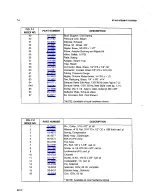
Page 30: ...ST AG STEAM IT cooKER S2127 ...

Page 31: ...pI 10 32 22 10 6969 Lug ground 23 10 3360 Elbow 90 brass 1 81PS x 3 160 0 24 95 3190 Body Assy 25 95 0115 Fulcrum and Drain Assembly see Figure 7 6 26 10 1945 Screw mach rnd hd stl cadmium pI 1 4 20 x 5 8 27 95 0918 Inner Case Adapter left side 28 10 1863 Screw mach phil tr hd st stl 6 32 1 4 29 95 3766 Access Cover pressure regulator 30 10 4667 Button plug 1 1 4 dia 31 10 6924 Plate serial 32 95 ...

Page 32: ...Figure 7 2 64A 09 6544 Exhaust Valve 120V 60 Hz New Style see pg 7 11 65 10 1956 Screw phil tr hd type A steel nickel pI 8 x 3 8 66 95 3189 Deflector Plate Exhaust Valve 67 95 6017 Kit Corrosion Rod Not Shown NOTE Available at local hardware stores FIG 7 2 PART NUMBER DESCRIPTION INDEX NO 1 10 1663 Pin Cotter 1 16 x1 2 st stl 2 10 2425 Washer 10 Flat 3 16 10x 1 2 00 x 086 thick cad pI 3 10 4675 Sp...

Page 33: ...o PARTS LIST ILLUSTRATE _ 16 2 o 0 I e Assembly h ust Va v Steam Ex a Figure 7 2 7 5 52127 ...

Page 34: ...7 6 ST AGSTEA M ITCOOKER S2127 ...

Page 35: ...2 95 3705 Bracket Pilot Light 23 10 307 Knob Timer 24 95 0462 Bracket Timer 25 95 3393 Timer 60 Minute 120V Special 26 10 1747 Screw Mach Rnd Hd St Stl 8 32 x 5 8 27 10 166 Terminal Strip 28 10 682 Buzzer 120V 29 10 1722 Screw Mach Rnd Hd St Stl 6 32 x 3 8 30 10 7697 Electrode 30A 95 3769 Insulator Electrode Not Shown 30B 10 7698 Lead Wire High Voltage Not Shown 30C 10 7699 Lead Wire Low Voltage N...

Page 36: ...gas 3 8 NPT 51 95 3829 Gas Shutoff Valve Installation Kit not shown 52 10 1759 Screw rnd hd 10 32 x 3 8 stl 53 10 2505 Lockwasher 10 54 10 2340 Nut 10 32 55 10 2347 Stud Receiver NOTE Available at local hardware store Figure 7 4 Door Assembly FIG 7 4 INDEX NO PART NUMBER DESCRIPTION 1 10 1776 Screw 10 32 x 1 2 long st stl 2 10 6765 Bearing spring pivot 3 10 7980 Spring door lift left hand 4 10 798...

Page 37: ... 1 3 8 special 4 95 0120 Spacer bearing 5 95 0198 Bearing 6 10 0050 Knob door latch 7 10 2517 Lockwasher internal tooth st stl 3 8 8 95 0136 Door Lock Casting AS5y 9 10 2359 Nut acorn alum 1 4 20 10 95 0658 Stud handle bearing 11 10 1731 Screw mach rd hd st stl 1 4 20 x 5 8 12 10 2513 Lockwasher internal tooth st stl 1 4 13 95 0659 Handle Bearing Bracket A55Y 14 95 0134 Handle door NOTE Available ...

Page 38: ...Dram Assembly Items 1 15 Part No 95 0116 10 3111 10 2513 10 1790 10 2318 10 2514 95 0198 95 0120 10 1999 95 0149 10 1763 10 2087 10 2358 10 3116 95 0115 95 0658 10 2227 10 2359 95 2604 Part No 10 3116 10 1999 10 2358 10 2087 10 3111 10 2513 10 1763 95 0120 95 0198 10 3111 10 2513 10 1790 10 2514 10 2318 95 3850 10 1041 95 3992 ST AG STEAM IT COOKER I I L J y l B O FULCRUM DRAIN ASSEMBLY The Fulcru...

Page 39: ... gauge B Remove flue enclosure C Remove old exhaust valve by unscrewing 114I P S nipple from cylinder O Remove safety reliefvalve assy from II2I P S nipple E Remove all fittings from the reducing tee and remove tee and nipple by unscrewing nipple from cylinder remount nipple and tee in the front 1 4 I P S tap hole Note that the use of the rear 1 4 I P S tap hole is eliminated install plug as shown...

Reviews: