background image

DESKTOP PRINTER SERVICE MANUAL

58

10. 

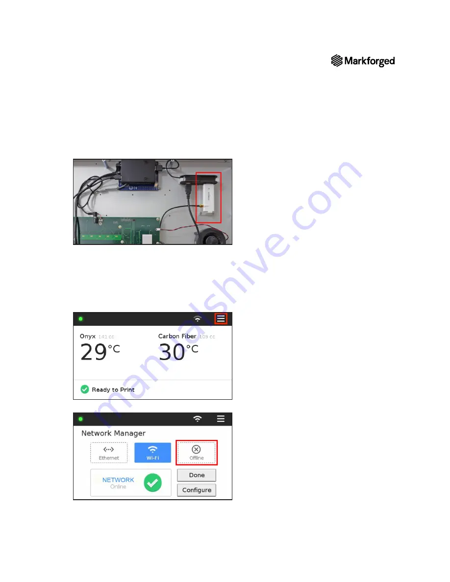
Unplug the Wi-Fi module (white in the photo below) from the USB hub in the base of the printer. 

11. 

Reinstall the bottom plate of the printer and the ten screws that hold it in place. 

12. 

Carefully turn the printer upright.

13. 

Remove and discard the tape holding the lid and visor shut.

14. 

Reinstall the print bed and reconnect the plastic feed tube to the plastic extruder.

15. 

Plug in and power on your printer. 

16. 

Select the Wi-Fi or Ethernet icon from the dashboard. 

17. 

Press the 

Offline

 tile to prevent the printer from using extra resources to search for wireless networks. 

18. 

Select 

Done

.

19. 

Reload material before attempting to print.

Summary of Contents for MARK TWO

Page 1: ...1 DESKTOP PRINTER SERVICE MANUAL DESKTOP PRINTER SERVICE MANUAL ...

Page 2: ...ion of this document visit our support website Copyright 2019 Markforged Inc All rights reserved Changesareperiodicallymadetotheinformationherein which will be incorporated in revised editions of this publication Markforged may make changes or improvements to the product s described in this publication at any time and without notice Version 1 2 January 2020 ...

Page 3: ...ER 9 REPLACING THE PLASTIC EXTRUDER 11 A1095 EXTRUDER REPLACEMENT A3648 EXTRUDER REPLACEMENT REPLACING THE XY STEPPER MOTORS 20 REPLACING THE PRINT HEAD 22 REPLACING THE MOTHERBOARD 27 REPLACING THE PRINT VISOR 31 REPLACING THE TENSIONER ASSEMBLY 33 REPLACING THE TOUCHSCREEN 37 REPLACING THE BEAGLEBONE 41 REPLACING THE RIBBON CABLE 46 REPLACING THE Z AXIS LEAD SCREW 54 DISABLING THE WI FI ADAPTER ...

Page 4: ... fuses may be used as replacements Third party substitutes are not permitted NOTE ON FIBER CAPABILITY This Service Manual covers all models of Markforged Desktop Series printers If your printer model is not fiber capable some of the sections in this Service Manual may not apply Such sections will be marked with the icon to the left A1095 AND A3648 EXTRUDERS The photos in the User Guide and Service...

Page 5: ...ed product label on the back panel PRESERVING FACTORY CALIBRATION Note that the plastic extruder and print head are factory calibrated do NOT adjust or disassemble in any way unless specifically instructed to do so by Markforged Support Warranty claims for assemblies that have been adjusted disassembled or modified may not be honored ...

Page 6: ...the bottom panel in place Note The color of the metal BeagleBone cover may vary the boards themselves are identical 9 Remove and set aside the bottom panel VERIFY CONNECTIONS TO BEAGLEBONE AND MOTHERBOARD 1 Disconnect all of the cables on the left and right sides of the BeagleBone with the exception of the grey cable Disconnect the grey cable from the green motherboard but leave it connected to th...

Page 7: ...7 DESKTOP PRINTER SERVICE MANUAL ...

Page 8: ...verify that it is secure at both ends 4 If there is a USB cable attached to the motherboard verify that it is secure at both ends CLEANUP 1 Replace the panel and reinstall all 10 screws 2 Carefully turn the printer upright 3 Remove and discard the tape holding the lid and visor shut 4 Reinstall the print bed 5 Reinstall the Wi Fi antenna Ethernet cable 6 Reconnect the plastic feed tube to the plas...

Page 9: ... Temperature Control Cool Note The print head may take several minutes to completely cool 3 Power off your printer and manually move the print head away from the extruders 4 Using the 2mm hex key slightly unscrew the top left socket head cap screw on the fiber extruder Note Do not unscrew it all the way It should require no more than one full turn to loosen 5 Remove the fiber Bowden tube from the ...

Page 10: ...ove the fiber extruder FIBER EXTRUDER REPLACEMENT 1 Insert the 3 wire and 4 wire connectors into the corresponding ports on the new fiber extruder and ensure that they are plugged in all the way 2 Seat the new fiber extruder on the printer chassis such that the keyhole slots on the extruder bracket align with the screws 3 Tighten the four screws that connect the base of the extruder to the chassis...

Page 11: ...dure applies to you then follow the instructions in the corresponding subsection to replace your plastic extruder Tools 2mm hex key 2 5mm hex key A1095 EXTRUDER REPLACEMENT Remove A1095 extruder 1 Completely unload all print materials For more information see Unloading Plastic and Unloading Fiber if applicable in the User Guide 2 Cool the print head Menu Utilities Manual Control Temperature Contro...

Page 12: ...e way through the channel at the bottom of the plastic extruder toward the back of the printer 6 Unscrew the thumbscrew that connects the plastic Bowden tube to the plastic extruder 7 Remove the plastic Bowden tube from the plastic extruder and let it hang freely 8 Press on the push to connect fitting on the back of the plastic extruder to remove the plastic feed tube Let it hang freely 9 Using th...

Page 13: ...m the old extruder into the holes on the bracket and tighten them using the 2 5mm hex key 4 Slide the fiber feed tube through the channel at the bottom of the new plastic extruder toward the front of the printer 5 Slide the metal insert from the fiber feed tube into the V shaped groove on the right side of the fiber extruder and use the 2mm hex key to tighten the screw 6 Reinstall the plastic Bowd...

Page 14: ...e 2 Cool the print head Menu Utilities Manual Control Temperature Control Cool Note The print head may take several minutes to completely cool 3 Power off the printer and manually slide the print head away from the extruders 4 Use the 2mm hex key to loosen but not remove the top right socket head cap screw connecting the fiber feed tube to the fiber extruder 5 Detach the fiber feed tube from the f...

Page 15: ...gh the channel at the bottom of the plastic extruder toward the back of the printer 7 Unscrew the thumbscrew connecting the plastic Bowden tube to the plastic extruder 8 Press in on the push to connect fitting to remove the plastic feed tube from the plastic extruder ...

Page 16: ...m hex key remove and set aside the two screws securing the extruder to the rail 10 Unclip the cable from the wire management clip on the front face of the extruder then disconnect the 4 pin cable from the socket on the black inward face of the extruder ...

Page 17: ...ect the 6 pin cable from its connector on the front face of the extruder 12 Remove the plastic extruder and set it aside Replace A3648 extruder 1 Connect the 6 pin cable to its corresponding connector on the front face of the new plastic extruder ...

Page 18: ... clip on the front face of the extruder 3 Install the extruder on the rail pushing it back against the case until the mounting holes line up Use the 2 5mm hex key to install the two screws securing the extruder to the rail 4 Connect the plastic feed tube to the plastic extruder 5 Connect the plastic Bowden tube to the plastic extruder and tighten the thumbscrew ...

Page 19: ...ed tube into the slot on the fiber extruder then use the 2mm hex key to tighten the top right screw securing the fiber feed tube in place 8 Carefully tuck all internal cables and connectors below the lid of the printer 9 Power on the printer 10 Reload print material For more information see Loading Plastic and Loading Fiber if applicable ...

Page 20: ...k any wires or other components in the printer during this process Note Take care not to discard any hardware you remove during this procedure as you will need it during the reinstallation Tools 2 5mm hex key XY STEPPER MOTOR REMOVAL 1 Power off your printer 2 Using the 2 5mm hex key remove the four screws from the underside of the printer case shelf that connect it to the stepper motor and carefu...

Page 21: ...at the teeth of the belt mesh with the teeth on the pulley 2 Attach the 4 wire connector to the port on the front of the XY stepper motor 3 Place the new XY stepper motor on the metal shim so that the shim and motor are aligned with the screw holes in the printer case shelf 4 Using the 2 5mm hex key thread the four screws into the bottom of the printer case shelf and up into the XY stepper motor 5...

Page 22: ...it PRINT HEAD REMOVAL 1 Completely unload materials from your printer For more information see Unloading Plastic and Unloading Fiber if applicable in the User Guide 2 Cool the print head Utilities Manual Control Temperature Control Cool Note The print head may take several minutes to completely cool 3 Power off your printer 4 Remove the thumbscrews connecting both Bowden tubes to the print head Al...

Page 23: ...ICE MANUAL 5 Slide the ribbon cable clip away from the print head and the circuit board 6 Gently squeeze the tabs at the top and bottom of the ribbon cable connector to release it from the board Allow the cable to hang freely ...

Page 24: ...onnecting the print head to the print head base 8 Carefully pull the print head off of the print head base PRINT HEAD REPLACEMENT 1 Carefully place the new print head onto the print head base and hold it in place Ensure that you align the pins on the print head base with the holes on the print head so that the pins are not damaged ...

Page 25: ... Note Be careful not to break the cable clip or board Ensure that the cable is secure The clip will keep the cable from dragging on parts or becoming damaged 4 Reinstall both Bowden tubes and tighten the respective thumbscrews into the print head 5 Power on your printer 6 Reload print material into your printer For more information see Loading Plastic and Loading Fiber if applicable in the User Gu...

Page 26: ... menu options 10 Select the Print From Storage tile from the menu options 11 Select the file from the USB drive and press Print to update the offsets for the print head Note This print file may require specific materials to be loaded but will not actually print anything ...

Page 27: ... all print material from the printer For more information see Unloading Plastic and Unloading Fiber if applicable in the User Guide 2 Remove and set aside the print bed and any fiber spools 3 Power off your printer and unplug the power cord from the back panel 4 Remove and set aside the Wi Fi antenna Ethernet cable 5 Disconnect the feed tube from the plastic extruder Remove it from the printer and...

Page 28: ...screws connecting the motherboard to the printer and set them aside 12 Remove the motherboard from your printer MOTHERBOARD REPLACEMENT 1 Mount the new motherboard in place 2 Using the 2 5mm hex key reinstall the four screws that connect the motherboard to the printer 3 Carefully reconnect all nine connections to the board Note The ribbon cable bottom right in the photo below connects to a socket ...

Page 29: ...he plastic extruder 11 Plug the power cord in and turn the printer on Ensure that it boots successfully 12 Navigate to the Firmware Recovery utility Menu Utilities Maintenance Firmware Recovery and follow the onscreen instructions 13 Manually reboot your machine to finish the Firmware Recovery utility 14 Reload print material into your printer For more information see Loading Plastic and Loading F...

Page 30: ... Select the file from the USB drive and press Print to update the offsets for the print head Note This print file may require specific materials to be loaded but will not actually print anything 20 Adjust the XY offsets Menu Utilities Print Head Alignment Fiber Nozzle XY Offsets For more information see Adjusting the XY Offset in the User Guide ...

Page 31: ...ey to loosen the two bolts that secure the visor to the printer frame 2 Remove the bolts and washers from the printer and set them aside 3 Remove the caps from the outside of the visor and set them aside 4 Remove and set aside all other connection hardware see diagram below 5 Carefully remove the visor from the printer Before starting a print you should be sure to reinstall or replace your visor F...

Page 32: ... printer 2 Slide the spacers with the slots on the printer frame 3 Insert and align all other connection parts according to the image below 4 Reattach the visor caps on each side 5 Use the 4mm hex key to fasten the bolts at each connection point on the visor Note Tighten the bolts just enough to prevent the visor from closing under its own weight ...

Page 33: ...ng this procedure as you will need it during the reinstallation Tools 3mm hex key 2 5mm hex key TENSIONER ASSEMBLY REMOVAL 1 Power off your printer 2 Use the 3mm hex key to loosen the belt s tensioner by turning it 3 4 full rotations 3 Use the 2 5mm hex key to loosen and remove the two screws that hold the tensioner in place ...

Page 34: ...ex key push the shaft pin through the pulley and remove the pulley from the belt 5 When you remove the pin and pulley you will have five separate pieces One pin One pulley with old bearings still installed Two concave washers One tensioner assembly ...

Page 35: ...lley then wrap the belt around the pulley with its ribbed side facing inward Then insert the pulley with the washers still in place into the tensioner assembly 2 Use your finger to push the shaft pin through the hole in the tensioner assembly through the pulley and out the other side Ensure that the same length of pin protrudes equally on both sides of the pulley 3 After the pulley is successfully...

Page 36: ... SERVICE MANUAL 36 4 Reinstall the tensioner assembly and use the 2 5mm hex key to securely tighten the remaining two screws 5 Adjust the belt tension For more information see Adjusting Belt Tension in the User Guide ...

Page 37: ... and set aside the Wi Fi antenna Ethernet cable 4 Disconnect the feed tube from the plastic extruder Remove it from the printer and set it aside 5 Remove and set aside the print bed and any fiber spools 6 Tape the lid and visor of the printer closed to prevent them from accidentally opening 7 Carefully turn the printer upside down so that the bottom faces up and the back plate faces toward you 8 U...

Page 38: ...reen assembly to the printer casing and set them aside Note Each of these screws sits upon a plastic spacer two of these spacers sit between the BeagleBone cover and the touchscreen Ensure that you set these aside to be reinstalled later 14 Carefully remove the BeagleBone touchscreen assembly from your printer Note All four screws have additional spacers between the touchscreen and the printer cas...

Page 39: ... firm even pressure when inserting the pins 2 Align four white spacers with the holes around the touchscreen opening in the printer casing 3 Keeping the grey cable out of the way carefully seat the replacement touchscreen into its opening aligning the holes on the board with the spacers and the holes in the printer casing Note Ensure that the USB port on the BeagleBone faces toward the USB hub 4 P...

Page 40: ...ly Ensure that the screws pass through the spacers Note To avoid damaging the touchscreen do not over tighten the screws Hand tighten only until the screws are snug against the metal tabs 7 Re attach all five cables 8 Replace the bottom panel and securely fasten it using the ten Phillips screws you removed earlier 9 Carefully turn the printer upright 10 Remove and discard the tape holding the lid ...

Page 41: ...ormation see Unloading Plastic and Unloading Fiber if applicable in the User Guide 2 Power off and unplug the printer 3 Remove and set aside the print bed and any fiber spools 4 Remove and set aside the Wi Fi antenna Ethernet cable 5 Disconnect the feed tube from the plastic extruder Remove it from the printer and set it aside 6 Tape the lid and visor of the printer closed to prevent them from acc...

Page 42: ...er over the BeagleBone may be black silver or orange the color has no bearing on these instructions 11 Disconnect the four black cables on the left and right sides of the BeagleBone Do not attempt to disconnect the grey cable from the BeagleBone 12 Use the 2mm hex key to remove the two black screws that secure the BeagleBone cover to the touchscreen assembly 13 Disconnect the 3 wire connector at t...

Page 43: ...assembly Note the two white spacers that sit under the tabs on either side of the aluminum cover 16 Using the 2mm hex key remove the four screws attaching the BeagleBone to the aluminum cover then separate the BeagleBone from the cover BEAGLEBONE REPLACEMENT 1 Attach the new BeagleBone to the aluminum cover with the four screws 2 Align the BeagleBone over the touchscreen assembly and apply firm ev...

Page 44: ...4 Using a small zip tie secure the wires connecting the motherboard to the BeagleBone 5 Align the two white spacers with the holes in the touchscreen assembly then use the 2mm hex key to install the two screws that secure the aluminum cover to the printer casing 6 Plug the four black cables back into the BeagleBone ...

Page 45: ...ding the lid and visor shut 10 Reinstall the print bed 11 Reinstall the Wi Fi antenna Ethernet cable 12 Reconnect the plastic feed tube to the plastic extruder 13 Plug in and power on your printer Confirm that the BeagleBone touchscreen assembly is working properly 14 Update your printer s firmware For more information see Updating Firmware in the User Guide 15 Reload material before attempting to...

Page 46: ...ver Painter s tape or similar tape that will not leave residue on the printer Tape measure RIBBON CABLE REMOVAL 1 Unload all print material from the printer For more information see Unloading Plastic and Unloading Fiber if applicable in the User Guide 2 Power off and unplug the printer 3 Remove and set aside the print bed and any fiber spools 4 Remove and set aside the Wi Fi antenna Ethernet cable...

Page 47: ...e the four screws and the corresponding lock washers and set them aside 12 Remove the fan screen and set it aside 13 With the printer still upside down use the 2mm hex key to remove the 14 screws indicated below from the back plate of the printer 14 Untape the visor ...

Page 48: ...en it In the image below the arrow points toward the bottom plate of the printer facing up during the procedure 16 Find the spot where the ribbon cable adheres to the back wall of the printer and peel the cable free of the adhesive Note Leave the adhesive on the printer if possible You will need it when installing the new cable 17 Disconnect the ribbon cable from the motherboard Note that the cabl...

Page 49: ...he back plate away from the printer to create a gap wide enough to pass the ribbon cable through 19 Slide the ribbon cable through the new gap toward the opening for the fan 20 Feed the ribbon cable through the fan opening into the print chamber ...

Page 50: ... to disconnect the ribbon cable from the print head 22 Remove the ribbon cable from the printer RIBBON CABLE REPLACEMENT 1 Using the old cable as a reference fold the new cable in exactly the same position along the length of the cable 2 Slide the new ribbon cable between the cable cover and back plate so that it sits where the old cable sat ...

Page 51: ... the new cable to the back wall of the printer using the adhesive left over from the previous cable 4 Slide the cable cover back into place in the printer 5 Insert the clip on the new ribbon cable into the port on the bottom of the motherboard ...

Page 52: ...een as well as the four screws that hold it in place 7 Ensure that all parts of the printer are properly aligned and reinstall the fourteen screws into the back plate 8 Replace the bottom plate of the printer and reinstall the ten screws that hold it in place ...

Page 53: ...ibbon cable into its connector on the print head until both tabs snap into place then slide the cable clip back onto its bracket Note Be careful not to break the cable clip or board Ensure that the cable is secure The clip will keep the cable from dragging on parts or becoming damaged 13 Reinstall the print bed 14 Reinstall the Wi Fi antenna Ethernet cable 15 Reconnect the plastic feed tube to the...

Page 54: ... printer For more information see Unloading Plastic and Unloading Fiber if applicable in the User Guide 2 Power off and unplug the printer 3 Remove and set aside the Wi Fi antenna Ethernet cable 4 Disconnect the feed tube from the plastic extruder Remove it from the printer and set it aside 5 Remove and set aside the print bed and any fiber spools 6 Tape the lid of the printer closed to prevent it...

Page 55: ...inter s interior 11 Turn the lead screw counterclockwise to remove it from the print stage then pull the stepper motor and lead screw out of the bottom of the printer Note You may want to wear disposable gloves when handling the lead screw as it is coated in grease 12 Feed the new lead screw assembly through the opening in the bottom of the printer and tighten it until the stepper motor rests agai...

Page 56: ...tempting to print To ensure that your printer is ready to print see Z Axis Recalibration below Z AXIS RECALIBRATION 1 Spread synthetic grease on the lead screw 2 Manually move the print stage up and down to disperse the grease Ensure that the print stage can move the entire travel span of the Z axis 3 Start the Shim Bed Level utility For more information see Leveling the Print Bed in the User Guid...

Page 57: ...nformation see Unloading Plastic and Unloading Fiber if applicable in the User Guide 2 Power off and unplug the printer 3 Remove the Wi Fi antenna Ethernet cable 4 Disconnect the feed tube from the plastic extruder Remove it from the printer and set it aside 5 Remove and set aside the print bed and any fiber spools 6 Tape the lid and visor of the printer closed to prevent them from accidentally op...

Page 58: ...rn the printer upright 13 Remove and discard the tape holding the lid and visor shut 14 Reinstall the print bed and reconnect the plastic feed tube to the plastic extruder 15 Plug in and power on your printer 16 Select the Wi Fi or Ethernet icon from the dashboard 17 Press the Offline tile to prevent the printer from using extra resources to search for wireless networks 18 Select Done 19 Reload ma...

Reviews: