

CONFIDENTAL. DO NOT DUPLICATE OR REDISTRIBUTE
5
Pre-Install Guide_2.0.0 | September 11, 2018
PRE-INSTALLATION GUIDE : METAL X SYSTEM
METAL X
MOVING THE METAL X
An elevator is required to transport the Metal X between floors.
While lifting, be mindful of the upper (opaque) access panel. If it swings open as
you move the printer, you can repurpose some of the leftover blue tape to secure
it temporarily.
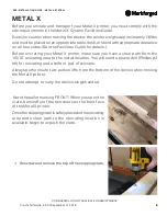
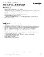
1. Use safe lifting techniques to remove the Metal X
printer from its crate. The printer weighs approximately
130lbs and is slightly top-heavy; we recommend that
two people lift the printer from the bottom while a
third steadies it near the middle.
The printer is solid across its bottom face, with no ridges
or protrusions. You should not need work gloves to lift
it. Be mindful of the bottom block in the crate -- lift the
printer straight up to avoid finger injury.
2. Set the Metal X up on an appropriate table, stand, or
bench with the necessary clearance on all sides. (See
the
Facilities Guide
for details.)
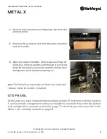
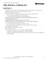
3.
Peel off the final layer of blue plastic from the chamber
door and discard it.