9
Document No:SM-412 Issue C 28.01.21 Marlec Engineering Co Ltd
ASSEMBLY
Place the Tower Base over the four threads protruding from the concrete foundation, ensuring the
pivot is orientated correctly. Fit the nuts and washers, and securely tighten.
Lay the tower tube in position on the ground with its bottom end in the tower base and insert the
M10 x 70 bolt, secure with the washer and nut ensuring the tube is free to pivot.
Attach the guys to the guy plates with the shackles through the looped ends of the guys, the 6.5m
guys are fitted towards the top of the tube, the 4.5m guys towards the bottom.
Fit the remaining 4 shackles to the guy ground anchors. Place the hooked ends of 2 of the rigging
screws through the shackles on the side anchor points. Open the rigging screws to approx ¾ their
maximum length.
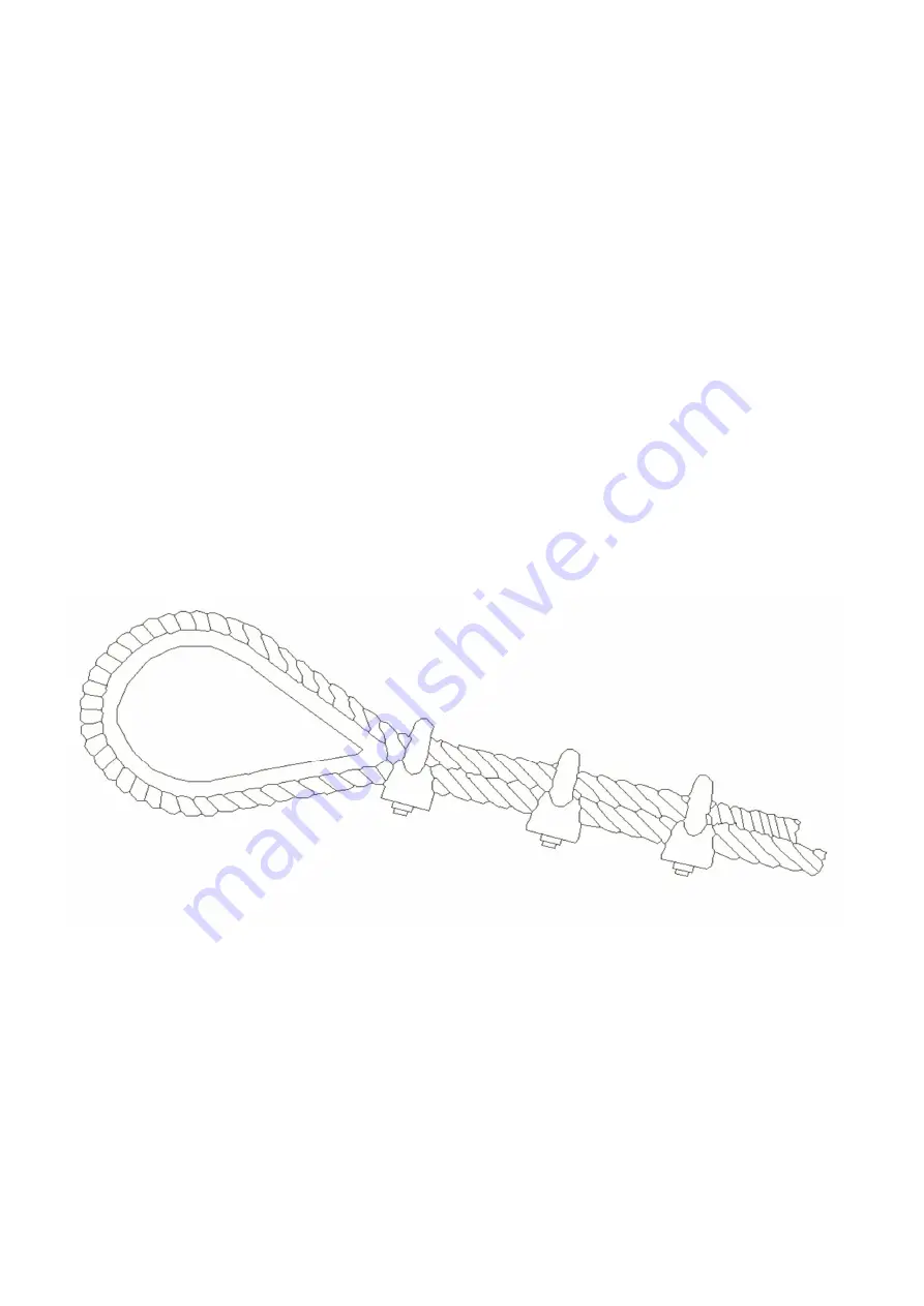
Take the 2 upper side guys and pass the free ends through the looped ends of the rigging screws and
around the thimbles pulling the cables to remove the slack, secure in position using 3 rope grips on
each guy. Repeat the procedure with the fore and aft guys by laying them alongside the side guys to
achieve the same length.
Note: If the ground is uneven or not level, the guy lengths may differ.
The first rope grip must be placed immediately against the thimble. The grips must be placed so that
they are separated by a minimum distance of 30mm. The ‘U’ bolt must always be placed on the tail
end of the rope i.e. non load bearing end.
Hook the rigging screw into the shackle on the anchor point for the rear guy, i.e. the anchor point
covered by the tower.
Fig 7


