Rutland 504 Windcharger Installation & Operation
Doc No: SM-150 Issue C 17.03.14 8 Marlec Eng Co Ltd
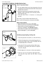
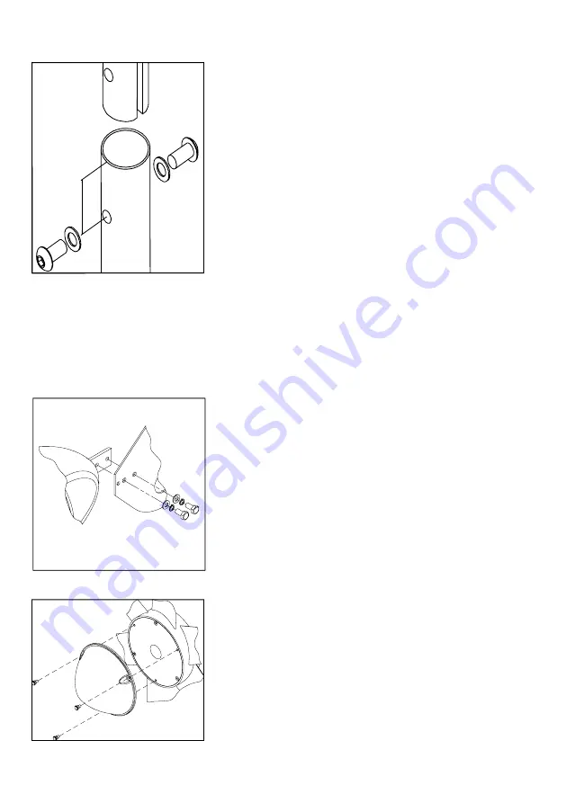
Tower Preparation (Fig.1)
1. The post adapter fitted to the 504 is designed to fit inside
a standard 31.7mm internal diameter tube. Max external
diameter 38.1mm (1½”).
2. Mark and centre-punch two positions diametrically
opposite, at 90° to the pipe seam if necessary, 40mm
from top of the tube.
3. Drill two holes 8.5mm in diameter on centre-punch
positions.
Note: When using the Rutland 504 Mounting Kits,
items 2 and 3 can be ignored, as these are pre-drilled
.
Marlec Tower Options
x
Rutland 504 Marine Mounting Kit
CA-12/01
x
Marine Stays Kit for use with Mount Kit
CA-12/32
x
Rutland 504 Land Tower & Rigging Kit for
temporary installations
CA-12/12 & CA-12/13
x
Tube sections to adapt to own pole arrangement -
1000mm
CA-12/15
or 500mm
CA-12/16
Fig 1
Fig 2 A
Fig 2 B
Post Adaptor
ї
40mm
ї
Assembly & Installation Detailed Instructions
Tail & Nose Assembly (Fig.2 A & Fig.2 B)
1. Place the generator, nose down, on a flat soft surface.
2. Fit the tail into position on the protruding portion of
casting ,ensuring the holes in the casting align with the
corresponding holes in the tail fin.
3. Secure the Tail fin in position with the 2 M6 screws
and washers, ensuring the plain washers are against
the tail fin. (Fig 2A)
4. Check tightness of all screws
. (Do not over-tighten).
5. Place the nose cone into position aligning the holes
and press the snap rivets into the holes to secure.
(Fig 2B)
Summary of Contents for Rutland 504 efurl
Page 2: ......

