Rutland FM1803-2
Installation & Operation
Document No: SM-146 Issue G 01.11.20
Marlec Engineering Co Ltd
11
Blade & Hub Assembly continued
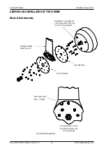
1. Prepare the rotor assembly - assemble the 3 turbine blades between the hub front and
rear plates, inserting the bolts through the rear plate, ensuring the flat side of the blade
faces the front plate. Fit all 9 bolts, washers & Ny lock nuts provided & secure tightly.
Ensure the 3 cut outs around the edge of the front plate align with the nose cone fixing
bosses.
2. Fit the rotor assembly onto the windshaft.
3. Put the spring washer over the end of the windshaft, it will pass through the hexagonal
hole in the front plate.
4. Thread the M24 nut onto the threaded end of the windshaft, until it just comes up
against the front plate.
5. Pull the rotor assembly forward slightly & rotate as necessary to align the hexagonal
hole in the front plate over the M24 nut.
6. Rotate the whole rotor assembly clockwise to thread the nut onto the windshaft. The
windshaft can be held using an 8mm Allen key in the socket in the end of the windshaft.
Alternatively hold the rotor assembly still & rotate the windshaft anticlockwise using the
8mm Allen key in the socket in the end of the windshaft.
7. Tighten the rotor onto the shaft to a torque of 30 - 50Nm, until the spring washer is
compressed, the rotor is secure & the rear plate is located against the shoulder on the
windshaft. Check the rotor for free rotation.
8. Fit the nose cone in position on the front of the rotor and secure in place with the 3
No10 x 9.5mm screws provided.
Alternatively, the turbine and nose cone can be fitted after mounting the generator assembly to
the tower.


