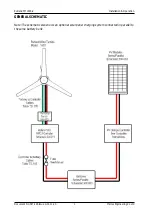
Rutland FM1803-2
Installation & Operation
Document No: SM-146 Issue G 01.11.20
Marlec Engineering Co Ltd
14
Control Unit Installation
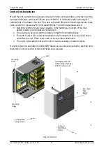
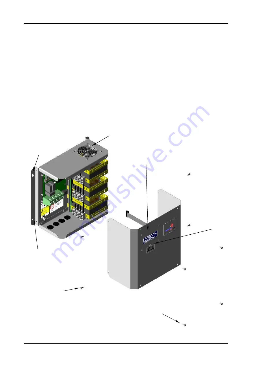
Mount the unit as shown below securely to a wall or other vertical surface, using the mounting
holes provided (hole centres are 285mm W x 205mm H), in a suitable location allowing for
cable entries in the base of the unit. The cable entries are fitted with blanking grommets, these
can be pierced or replaced with 20mm gland fittings. Follow these guidance notes:
•
Install the control unit as close as possible to the batteries, 2m length of the main
battery leads is recommended as a maximum.
•
The unit should be protected from battery fumes from vented batteries.
•
The control unit is fan cooled and ventilation of a minimum of 10cm is required above
and below the unit. These vents must not be covered or obstructed.
•
The unit is not weatherproof and therefore must be suitably protected indoors.
If selected, position and install the RUN/STOP Switch at a convenient location for shutting down
the turbine in the event the control unit needs to be isolated.
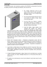
Fig 6. Control Unit
Run / Stall
Push
Button
LCD Display with rear
ribbon fixing. Unplug at
PCB to remove cover
Mounting
Holes
Mounting
Holes
Vent
4 x Panel
Front fixing
screws
4 x Panel Side
fixing screws


