Rutland FM1803-2
Installation & Operation
Document No: SM-146 Issue G 01.11.20
Marlec Engineering Co Ltd
17
ELECTRICAL CONNECTION
1. Using the cable selected (see Table 1), pass the cable through the inside of the tower &
route to the control unit. Leave enough length of cable protruding from the top of the tower
to enable easy connection to the wind generator.
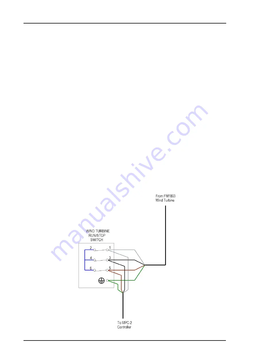
2. If selected install the separately supplied Run/Stop Switch following the wiring diagram Fig 9
at a suitable location close to the control unit or convenient for shutting down the turbine in
the event the control unit needs to be isolated. Set it at the STOP position.
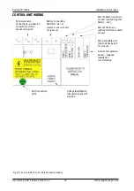
3. Remove the fixing screws from the control unit front panel, see Fig 6. As the panel lifts away
unplug the LCD connection ribbon cable from the PCB in the main housing.
4. Using the cables selected pass each through the grommeted holes in the base of the control
unit. The grommets can be replaced by M20 glands if preferred. Ensure the battery cables
are not yet connected to the battery, i.e. DO NOT MAKE LIVE CONNECTIONS
5. Make the connections following Figs. 10 and 11. Note that some connections are optional.
It is vital to observe correct polarity when connecting the battery cables otherwise serious
damage will result.
6. Offer up the front panel to the main unit and re-connect the display ribbon cable. Re-fit the
control unit front panel.
7. Proceed to joining the turbine fitted cables to the connecting cable at the top of the tower.
Fig 9. Run/Stop Switch Connections (optional)

