Rutland FM1803-2
Installation & Operation
Document No: SM-146 Issue G 01.11.20
Marlec Engineering Co Ltd
8
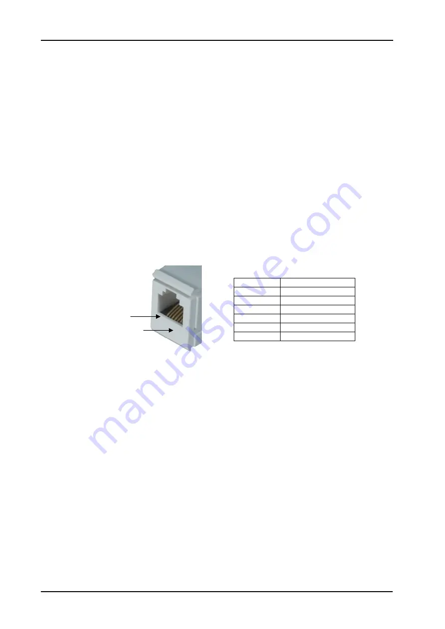
Pin 1
Pin 6
•
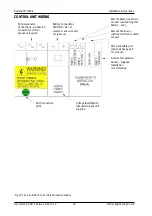
Remote Voltage Sensing feature – enables the user to connect fine wires to the battery
terminals over the distance to a battery located more than 2m cable distance away. See
Table 1. This senses actual battery voltage and the controller charges and regulates
based on this reading overcoming any voltage drop that may occur in the battery cables.
Note: Do not undersize longer battery cables’ current carrying capacity.
•
Remote Shutdown Connection feature – volt free contacts e.g. switch or relay contacts
connected across these terminals, provide a method of remotely shutting down the
turbine. Closed contacts to shut down the turbine, open contacts to run the turbine.
The LCD displays “REMOTE SHUTDOWN” when activated.
•
The control unit has a built
-
in cooling fan which will only operate when the internal
temperature of the control unit exceeds a pre-set level. This will only normally operate
during periods of high generated power levels.
•
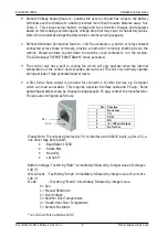
A RJ11 Serial Data output is provided for connection of other devices e.g. Computer
which can read serial data. This requires a special interface cable and PC app. Some
operating parameters can be changed using bespoke PC app, contact the manufacturer.
The pins are configured as follows:
Please Note: The output signal level is 5V, to interface with RS232 levels, eg for a PC, a
line driver may be required.
•
Baud Rate 115200
•
8 data Bits
•
No parity
•
1 stop bit
Battery Voltage: Text string "Batv" immediately followed by Integer value of voltage x
100 (*)
WG Current : Text String "Amps" immediately followed by integer value of current x
100 (*)
Mode : Text String “Mode" immediately followed by integer value.
0 = Run
1 = Manual Shutdown
2 = Over Voltage
3 = Rectifier Over Temperature
4 = Transformer Over Temperature
5 = Remote Shutdown
* ie 12.42 volts is output as 1242
Pin Function
1
Do not use
2
TX
3
GND
4
RX
5
+5v 100mA Output
6
Do Not Use


