


Rutland Furlmatic 910-4 Windcharger Installation & Operation
Doc No: SM-138 Iss. A 29.01.13
4
Marlec Eng Co Ltd
Choose a calm day to install the equipment and consider other safety aspects.
No attempt to repair the system should be made until the wind generator is
restrained from turning.
The Windcharger is fitted with ceramic magnets, which can be damaged by
heavy handling. The main generator assembly should be treated with care during
transit and assembly.
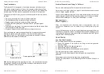
High winds – in high winds the Windcharger’s built-in thermostat may
operate to prevent the generator overheating. In this mode the output will cease
and the turbine will temporarily slow down until such time as the lower level
temperature is reached and the generator is once again connected and charging.
This may be seen to cycle in prolonged high winds particularly in high ambient
temperatures. Further the furling tail mechanism of the Furlmatic model will
operate in high winds orienting the turbine out of the prevailing wind direction to
slow the turbine down. It will return to face the wind as windspeeds fall and will
be seen to cycle during high wind speeds.
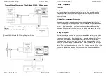
It is essential to observe the correct polarity when connecting the Windcharger
and all other components into an electrical circuit. Reverse connection will
damage the Windcharger and incorrect installation will invalidate the warranty
The fuse supplied must be fitted to protect the system.
If in doubt, refer to your dealer, a competent electrical engineer or the
manufacturer.
Check You Have Received
In the event of loss or damage, consult your dealer or the
manufacturer.
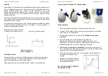
1 x main generator assembly
1 x tail assembly
24 x No. 10x25mm special self-
tapping screws
6 x aerofoil blades
1 x fuse and fuse holder
1 x 2-way terminal block
2 x M10 buttoncap screws
2 x M10 shakeproof washers
1 x 6mm Allen key
Rutland Furlmatic 910-4 Windcharger Installation & Operation
Doc No: SM-138 Iss. A 29.01.13
17
Marlec Eng Co Ltd
1.
Read the Electrical Connection
and
Up & Running
sections and be
satisfied that your system complies.
2.
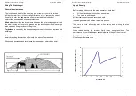
Is there sufficient wind?
The Rutland 910-4 needs approximately 5 knots
wind speed to start charging. The wind speed across the turbine blades
may be greatly reduced in built-up area compared with weather reports for
example.
3.
Static Tests:
Is the battery in good condition?
Check the voltage and
electrolyte level of each battery.
Check electrical continuity
throughout
the system, especially corrosion and poor connections in cable joins and
connector blocks.
4.
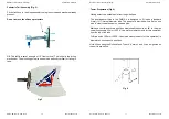
Running Tests:
Check for power output from the Windcharger,
following this procedure:
Set a digital multimeter to DC Amps, scale of between 5 and 10 if possible.
Connect the meter positive (+) probe to the wind generator output positive
cable and the meter negative (-) to the regulator input positive. Provided
there is sufficient wind there should be a current reading. This establishes
that power is being delivered.
Using the same multimeter setting as above measure between the regulator
to b and the b. Provided there is sufficient wind there should
be a current reading. This establishes if power is passing through the
regulator.
If both above are unsuccessful set the multimeter to DC Volts. Disconnect
the wind generator from the regulator and connect the meter + to the wind
gen + and the meter – to the wind gen -. Provided there is sufficient wind
there should be a variable voltage reading according to the speed of the
wind seen at the wind turbine. This will establish if the wind generator is
able to deliver power or not.
If tests A and C are successful but test B fails to produce results connect
the wind gen directly to the battery. Set the digital multimeter to DC Amps
and measure power between the wind gen + and the b. If a reading
is measured, providing there is sufficient wind, then the regulator is faulty.
If the wind turbine fails to deliver any current or open circuit V reading
undertake the further tests below.


