background image

Rutland Furlmatic 910-4 Windcharger                                                                                    Installation & Operation


Doc No: SM-138 Iss. A 29.01.13


14  

Marlec Eng Co Ltd


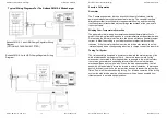
Typical Wiring Diagrams For The Rutland FM910-4 Windcharger 

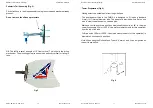
Rutland FM 910-3 with HRSi Charge Regulator Wiring 
Diagram 
( OPTIONAL SOLAR PANEL FITTED ) 

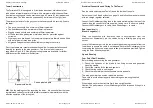
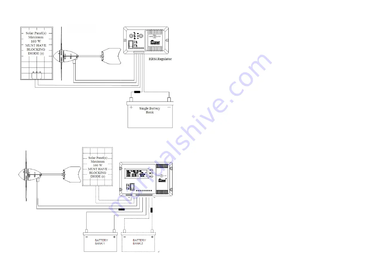
Rutland FM 910-3 with HRDi Charge Regulator Wiring 
Diagram 

Rutland Furlmatic 910-4 Windcharger                                                                                    Installation & Operation


Doc No: SM-138 Iss. A 29.01.13


7  

Marlec Eng Co Ltd


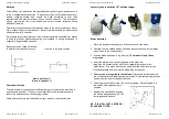
Principle Of Operation 


Generator 

 
The 3 phase ac generator is driven directly by the aerofoil blades, rotating 
permanent magnets around the fixed stator winding.  The variable frequency 
alternating current is rectified within the generator housing, and the resulting 
rectified current is transmitted via the sliprings and brushes at the yaw axis to 
the output cable. 
 

Winding Over-Temperature Protection 

 
The generator stator winding incorporates embedded thermal protection to 
protect the winding from damage due to over temperature during extreme winds. 
On reaching the thermal protection limit, the device will reduce generator output 
current to allow the winding to cool, whereupon normal performance will be 
resumed.  If the thermal protection is active, the turbine may reduce to a slow 
rotational speed with a corresponding reduction in charge current, this is normal. 
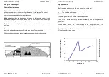
 

Furling Tail System


The tail assembly is designed to direct the turbine into the main direction of the 
wind at windspeeds up to approx 15m/s.  Above this the automatic “furling” 
mechanism is activated to turn the generator at an angle to the wind to protect 
the turbine, generator and supporting structure from severe electrical and 
mechanical loads due to high winds.  When the wind speed subsides, the tail 
assembly will automatically return the turbine to normal operation.  In prolonged 
gusty & turbulent conditions, the system may be seen to repeat this cycle many 
times.  Power will be reduced during furling.  For effective operation of the furling 
system the wind turbine must be sited to ensure it is as free as possible from 
turbulence and in a stable upright position.  

Summary of Contents for Rutland FM910-4

Page 1: ...Solar power that works with your Rutland Windcharger Energy saving solar panels for your home Solar power to keep your batteries topped up on board Rutland Furlmatic 910 4 Windcharger Installation Operation Doc No SM 138 Iss A 29 01 13 Marlec Eng Co Ltd Rutland FM910 4 Windcharger 12V or 24V Owners Manual Installation and Operation Doc No SM 138 Iss A 29 01 13 ...

Page 2: ...re in the seller s opinion defective and are so found by Marlec upon inspection A valid proof of purchase will be required if making a warranty claim Defective parts must be returned by prepaid post to the manufacturer Marlec Engineering Company Limited Rutland House Trevithick Road Corby Northamptonshire NN17 5XY England or to an authorised Marlec agent This Warranty is void in the event of impro...

Page 3: ...very best out of the Rutland FM 910 4 we recommend that you read this manual and familiarise yourself with its contents before installing and operating the Windcharger system Summary of Features and Uses Automatic furling tail fin directs turbine out wind above 16m s for gale protection Low wind speed start up maximises power generation in low winds High grade construction materials for durability...

Page 4: ...Installation Operation Doc No SM 138 Iss A 29 01 13 17 Marlec Eng Co Ltd 1 Read the Electrical Connection and Up Running sections and be satisfied that your system complies 2 Is there sufficient wind The Rutland 910 4 needs approximately 5 knots wind speed to start charging The wind speed across the turbine blades may be greatly reduced in built up area compared with weather reports for example 3 ...

Page 5: ... for tightness Check all other nuts bolts and screws for tightness Check the yaw axis for free rotation Check the tail fin moves freely Check tower assembly for condition Check the tension of the guy wires if applicable The tension of guy wires should be checked frequently during the first year The unit can be wiped with a mild detergent and rinsed with water to remove dirt and debris Troubleshoot...

Page 6: ...sh with height and can be overcome simply by putting the machine sufficiently high above them as shown Wind speed decreases and turbulence increases where obstructions exist Rutland Furlmatic 910 4 Windcharger Installation Operation Doc No SM 138 Iss A 29 01 13 15 Marlec Eng Co Ltd Up and Running Before raising and securing the wind generator check that All final mechanical checks have been made T...

Page 7: ...age due to over temperature during extreme winds On reaching the thermal protection limit the device will reduce generator output current to allow the winding to cool whereupon normal performance will be resumed If the thermal protection is active the turbine may reduce to a slow rotational speed with a corresponding reduction in charge current this is normal Furling Tail System The tail assembly ...

Page 8: ...voted pole Base pivoted with Rutland Furlmatic 910 4 Windcharger Installation Operation Doc No SM 138 Iss A 29 01 13 13 Marlec Eng Co Ltd Electrical Connection and Fitting To The Tower Run the cable selected see Table 1 down the inside of the pole Select one of the 2 basic systems on page 14 and follow the manual provided with the charge regulator selected Connect the Windcharger flying lead to th...

Page 9: ...ld be in accordance with table 1 The use of a smaller cable than recommended will reduce the performance of the charging system Cable and connectors are available from your dealer or the manufacturer Rutland Furlmatic 910 4 Windcharger Installation Operation Doc No SM 138 Iss A 29 01 13 9 Marlec Eng Co Ltd Assembly and Installation Of The Windcharger Blade Assembly 1 Place the generator assembly o...

Page 10: ... No SM 138 Iss A 29 01 13 11 Marlec Eng Co Ltd Tower Preparation Fig 6 Having selected a suitable pole from the guidelines The post adaptor fitted to the FM910 4 is designed to fit inside a standard 41mm 1 internal diameter tube The adaptor is provided with a flat on one side to clear the weld seam on seamed pipe Mark and centre punch two positions diametrically opposite at 90 to the pipe seam if ...

Reviews:

Related manuals for Rutland FM910-4