

Rutland Furlmatic 910-4 Windcharger Installation & Operation
Doc No: SM-138 Iss. A 29.01.13
8
Marlec Eng Co Ltd
Tower Construction
The Furlmatic 910-4 is designed to fit inside an aluminium, stainless or steel
tube with an internal diameter of 41mm with a minimum wall thickness of 5mm.
A suitable mounting pole can be erected using a 6.5 metre (21 feet) galvanised
(medium) tube. The tube must be supported by a minimum of four guy lines.
The attachment points for the guy lines to the tower should be securely fixed to
the tower.
The guy wires should be a minimum of 4mm in diameter.
The shackles should be a minimum of 5mm in diameter.
Rigging screws should be a minimum of 5mm in diameter.
All items should be galvanised or stainless steel for protection against
corrosion.
Where guy lines are looped, the loop must incorporate a thimble and be fitted
with a minimum of three rope grips.
All ground fixings must be made suitable according to the terrain.
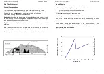
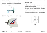
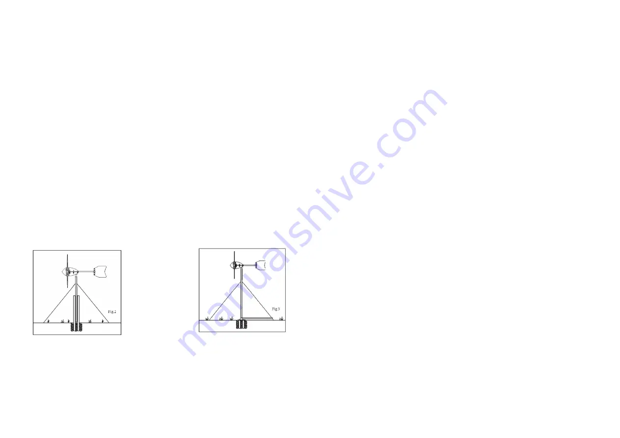
Pivot type towers are recommended as these allow for easier installation and
lowering for access to the wind generator. Two forms of pivot tower are
suggested in Figs 2 & 3. Non-guyed pivoting towers are available, for further
details contact the dealer or manufacturer.
NB: See the warnings section regarding the tower. It is essential that the tower
is maintained vertically to minimise lateral movement which interferes with the
effective operation of the furling tail.
Centre pivoted pole
Base pivoted with
Rutland Furlmatic 910-4 Windcharger Installation & Operation
Doc No: SM-138 Iss. A 29.01.13
13
Marlec Eng Co Ltd
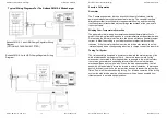
Electrical Connection and Fitting To The Tower
Run the cable selected (see Table 1) down the inside of the pole.
Select one of the 2 basic systems on page 14 and follow the manual provided
with the charge regulator selected.
Connect the Windcharger flying lead to the cable protruding from the top of the
tower using the connector block supplied, taking care to observe polarity.
Connect the Windc to cable + and Windcharger – to cable –
Red is positive (+)
Black is negative (-)
Wrap the connection with insulation tape to secure/protect from the
environment. Alternatively join the cables using a latching type plug and
socket.
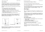
Locate the Windcharger into the tower whilst gently easing the cable from the
tower base to ensure the cable is not trapped. Secure the Windcharger to the
tower using the button cap screws and shake-proof washers provided. Tighten
using the 6mm Allen key supplied.
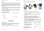
Up and Running
Four Point Final Checklist
Before raising and securing the wind generator:
1. Check the tightness of the blade & tail fixing screws and generator
mounting screws.
2. Check free rotation of the hub and yaw axis.
3. Check that the cable is not trapped.
4. Check that all electrical connections are secure and safe.
The wind generator can now be raised into position.
Take care to avoid all moving parts when raising and lowering the wind
generator.
When raised, secure the structure firmly in an upright position.
Caution-The performance of your Windcharger will be impaired if the pole is
not vertical.


