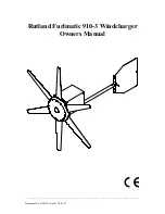
background image

_________________________________________________________________________________________

Document No: SM124 Issue D 30.01.07    


Rutland Furlmatic 910-3 Windcharger 

Owners Manual 


Summary of Contents for Rutland Furlmatic 910-3

Page 1: ..._________________________________________________________________________________________ _ Document No SM124 Issue D 30 01 07 Rutland Furlmatic 910 3 Windcharger Owners Manual ...

Page 2: ... CHECK YOU HAVE RECEIVED 4 WHAT YOU WILL NEED 4 SITING THE WINDCHARGER 5 PRINCIPLE OF OPERATION 6 TOWER CONSTRUCTION 7 ASSEMBLY INSTALLATION 8 Blade Assembly 8 Furlmatic Tail Assembly 9 Tower Preparation 10 BATTERIES 11 CABLE SPECIFICATION 12 ELECTRICAL CONNECTIONS FITTING TO TOWER 12 Final Mechanical Check 13 BASIC WIRING DIAGRAMS 14 UP RUNNING 15 SPECIFICATION PERFORMANCE 15 INSPECTION MAINTENAN...

Page 3: ...ted tower will experience lateral movement particularly in high winds and furling will be adversely affected will potential damage to the wind turbine When turning the Windcharger is capable of generating voltages in excess of the nominal voltage The turbine must never be allowed to rotate unless it is electrically connected to a regulator or batteries Avoid applying a short circuit to the Windcha...

Page 4: ...nless used in conjunction with a controller that is already fitted with a charge fuse High winds in high winds the Windcharger s built in thermostat may operate to prevent the generator overheating In this mode the output will cease and the turbine will temporarily slow down until such time as the lower level temperature is reached and the generator is once again connected and charging This may be...

Page 5: ...ap screws 2 x M10 shakeproof washers 1 x 6mm Allen key In the event of loss or damage consult your dealer or the manufacturer WHAT YOU WILL NEED Tools Suitable wire stripper Small terminal screwdriver Large flat blade screwdriver Crosshead screwdriver 10mm Spanner Other Items You Will Need Tower Mounting pole Batteries Battery terminals Cable Connector blocks as determined by your total system Oth...

Page 6: ...ulence Wind sheer describes the interference between the fast moving upper air and the slow moving air close to the ground and the resulting decrease in average wind speed as one gets closer to the ground Turbulence is caused by the wind passing over obstructions such as trees and buildings Both wind sheer and turbulence diminish with height and can be overcome simply by putting the machine suffic...

Page 7: ...put current to allow the winding to cool whereupon normal performance will be resumed If the thermal protection is active the turbine may reduce to a slow rotational speed with a corresponding reduction in charge current this is normal Furling Tail System The tail assembly is designed to direct the turbine into the main direction of the wind at windspeeds up to approx 15m s Above this the automati...

Page 8: ...nimum of 5mm in diameter Rigging screws should be a minimum of 5mm in diameter All items should be galvanised or stainless steel for protection against corrosion Where guy lines are looped the loop must incorporate a thimble and be fitted with a minimum of three rope grips All ground fixings must be made suitable according to the terrain Centre pivoted pole Base pivoted with gin pole Pivot type to...

Page 9: ...d Insert the protrusion at the trailing edge of the blade root fixing first into socket to align with the corresponding recess in the blade socket The blade can then be easily inserted with a lever action Gentle assistance with a soft faced mallet may be required 3 Four screws are required for each blade First secure each blade with two of the special self tapping screws provided 4 Fit the remaini...

Page 10: ...addle on the underside front of the housing Ensure the tail assembly is the correct way up refer to pictures in this manual the text on the tail label 4 Re fit bolt washers nut removed in 2 passing the bolt through the tail boom and windshaft housing Tighten all fasteners 5 Replace cover Note Do not remove the silicone protectors from the tail stops Tail Boom Fasteners NB The tail fin is set at an...

Page 11: ... a standard 41mm 1 internal diameter tube The adaptor is provided with a flat on one side to clear the weld seam on seamed pipe 2 Mark and centre punch two positions diametrically opposite at 90 to the pipe seam if necessary 20mm NOTE Use metric measurements for this operation from the top of the tube 3 Drill two holes 10 5mm NOTE Use metric measurements for this operation in diameter on centre pu...

Page 12: ...the battery and ensure system reliability during periods of low wind Permanent connections should always be made to the battery terminals Never use crocodile clips or similar devices Battery terminals should be well greased with petroleum jelly or similar We strongly recommend that one of the voltage regulators available from Marlec is fitted to prevent batteries becoming overcharged in strong win...

Page 13: ... 46 80 10 6 ELECTRICAL CONNECTION FITTING TO THE TOWER 1 Run the cable selected see Table 1 down the inside of the pole 2 Select one of the 2 basic systems on page 14 and follow the manual provided with the charge regulator selected 3 Fit the in line fuse and fuse holder in the circuit where the HRS type or no regulator is used It is essential that a charge fuse is fitted but note that some Marlec...

Page 14: ...to secure protect from the environment Alternatively join the cables using a latching type plug and socket 6 Locate the Windcharger into the tower whilst gently easing the cable from the tower base to ensure the cable is not trapped Secure the Windcharger to the tower using the button cap screws and shake proof washers provided Tighten using the 6mm Allen key supplied FINAL MECHANICAL CHECK 1 Chec...

Page 15: ...___________________________________________________ Document No SM124 Issue D 30 01 07 14 FM910 3 WIND GENERATOR BATTERY BATTERY RED BLACK FM910 3 WIND GENERATOR REGULATOR RED BLACK BROWN BLACK RED CHARGE FUSE BATTERY Charge Controller Wiring Diagram Regulator and Fuse Wiring Diagram ...

Page 16: ...connections are secure and safe The wind generator can now be raised into position Take care to avoid all moving parts when raising and lowering the wind generator When raised secure the structure firmly in an upright position The performance of your Windcharger can be impaired if the pole is not vertical SPECIFICATION AND PERFORMANCE 0 2 4 6 8 10 12 14 0 5 10 15 20 25 30 35 40 WINDSPEED M S CHARG...

Page 17: ...king the ground Take care that all persons are clear of the area The turbine will eventually slow down Tie a blade to the mounting pole to prevent it from rotating 2 If the tail boom is safely accessible using the tail boom rotate the generator out of the wind the turbine will eventually slow down Tie a blade to the mounting pole to prevent it from rotating Whilst the generator is stationary the f...

Page 18: ...eter to DC Amps scale of between 5 and 10 if possible Connect the meter positive probe to the wind generator output positive cable and the meter negative to the regulator input positive Provided there is sufficient wind there should be a current reading This establishes that power is being delivered B Using the same multimeter setting as above measure between the regulator to battery and the batte...

Page 19: ...posits from slipring with emery paper Heavy deposits and reduced power indicate a possible reverse connection to the battery see Page 11 Check hub for free rotation with generator disconnected from battery If the hub does not rotate freely check for a possible short circuit in the wiring If no wiring fault is found refer to your dealer or manufacturer If the above checks have identified a need for...

Page 20: ...Marlec Eng Co Ltd Installation Instructions __________________________________________________________________________________________ Document No SM124 Issue D 30 01 07 19 Notes ...

Page 21: ...Marlec Eng Co Ltd Installation Instructions __________________________________________________________________________________________ Document No SM124 Issue D 30 01 07 20 Notes ...

Page 22: ...rby Northamptonshire NN17 5XY England or to an authorised Marlec agent This Warranty is void in the event of improper installation owner neglect misuse damage caused by flying debris or natural disasters including lightning and hurricane force winds This warranty does not extend to support posts inverters batteries or ancillary equipment not supplied by the manufacturer No responsibility is assume...

Reviews:

Related manuals for Rutland Furlmatic 910-3