background image

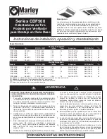
CAUTION - TO REDUCE RISK OF FIRE AND ELECTRIC

SHOCK OR INJURY TO PERSONS, OBSERVE THE

FOLLOWING:

1. To prevent electrical shock, disconnect all power coming to

heater at main service panel before wiring or servicing.

2. All wiring must be in accordance with the National and Local

Electrical Codes and the heater must be grounded as a pre-

caution against possible electric shock.

3. Verify the power supply voltage coming to heater matches

the ratings printed on the heater nameplate before energiz-

ing.

4. This heater is intended for ceiling installation ONLY. Do not

install the heater closer than 12” (305 mm) to any wall for

4000W models and 24” (609 mm) to any wall for 5000W

models.

5. Do not insert or allow foreign objects to enter any ventilation

or exhaust opening as this may cause an electric shock, fire,

or damage to the heater.

6. To prevent a possible fire, do not block air intakes or

exhaust in any manner. Keep combustible materials, such

as crates, drapes, etc., away from heater.

7. A heater has hot and arcing (sparking) parts inside. Do not

use it in areas where gasoline, paint, or flammable liquids

are used or stored.

8. This heater is not approved for use in corrosive atmos-

pheres such as marine, green house, or chemical storage

areas.

9. The heater enclosure must be securely mounted to ceiling

or framing capable of supporting the heater (45 lbs/20.4 kg).

Failure to do so could allow heater to fall.

10. Do not operate heater without outlet grilles installed. When

installing grilles with louver guides, make sure guides drop

into position so they cannot slide out during use.

Installation, Operation & Maintenance Instructions

SAVE THESE INSTRUCTIONS

WARNING

!

CDF500 Series

Ceiling Mounted

Fan Forced Heaters

Specifications

Surface Mounted

Model

Kw

1

BTU/Hr. (000)

Volts

Phase

2

Amps

3

CFM (dm3/s)

°F

4

CDF552SE

5/3.8/2.5

17.2/13.0/8.5

240

1-3

20.8/15.8/10.4

283 (133.5)

45

CDF547SE

4/3/2

13.7/10.2/6.8

277

1

14.5/10.8/7.2

283 (133.5)

51

CDF548SE

4/3/2

13.7/10.2/6.8

208

1-3

19.2/14.4/9.6

283 (133.5)

51

CDF557SE

5/3.8/2.5

17.2/13.0/8.5

277

1

18.1/13.7/9.0

283 (133.5)

45

CDF558SE

5/3.8/2.5

17.2/13.0/8.5

208

1-3

24.0/18.2/12.0

283 (133.5)

45

Recessed Mounted

Model

Kw

1

BTU/Hr. (000)

Volts

Phase

2

Amps

3

CFM (dm3/s)

°F

4

CDF552RE

5/3.8/2.5

17.2/13.0/8.5

240

1-3

20.8/15.8/10.4

283 (133.5)

45

CDF547RE

4/3/2

13.7/10.2/6.8

277

1

14.5/10.8/7.2

283 (133.5)

51

CDF548RE

4/3/2

13.7/10.2/6.8

208

1-3

19.2/14.4/9.6

283 (133.5)

51

CDF557RE

5/3.8/2.5

17.2/13.0/8.5

277

1

18.1/13.7/9.0

283 (133.5)

45

CDF558RE

5/3.8/2.5

17.2/13.0/8.5

208

1-3

24.0/18.2/12.0

283 (133.5)

45

(1) Factory wired for highest wattage, field convertible to lower wattages.

(2) Factory wired 1Ø, field convertible to 3Ø.

(3) On dual phase units, maximum amp draw is listed.

(4) Temperature difference at highest rated wattage.

Description

Marley downflow ceiling mounted heaters are designed for

recessed or surface applications. Surface mounted heaters

extend only six inches into the room. Recessed mounted

heaters recess only seven inches into the ceiling. Mounts

easily into 2 X 2 foot ceiling grids.

Summary of Contents for CDF547RE

Page 1: ... operate heater without outlet grilles installed When installing grilles with louver guides make sure guides drop into position so they cannot slide out during use Installation Operation Maintenance Instructions SAVE THESE INSTRUCTIONS WARNING CDF500 Series Ceiling Mounted Fan Forced Heaters Specifications Surface Mounted Model Kw1 BTU Hr 000 Volts Phase2 Amps3 CFM dm3 s F4 CDF552SE 5 3 8 2 5 17 2...

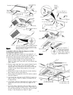
Page 2: ...e refer to Field Conversion for Lower Wattage Rating or Conversion for 3ø Installation on page 7 and wiring diagrams Figure 13 page 7 10 Position the heater section over the studs on the surface mounting plate Figure 2 NOTE The end of the heater section with the terminal block must be positioned at the end of the surface mounting plate where the supply wiring enters 11 Push the heater section onto...

Page 3: ...duce wattage or convert from single to three phase voltage refer to Field Conversion for Lower Wattage Rating or Conversion for 3ø Installation on page 7 and wiring diagrams Figure 13 page 7 3 Nut 4 Screws or Bolts Not Supplied Screw 4 Thumb Pin Hole 2 Insure that Thumb Pin is pulled out before positioning the surface mounting enclosure on the heater section Depress Thumb Pin after surface enclosu...

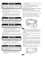
Page 4: ... Warning No 9 page 1 2 Cut a 221 4 x 221 4 565 mm x 565 mm mounting hole in the ceiling for the recess mounting box Figure 5 3 Remove Recess Mounted Heater assembly from carton Heater assembly includes 1 recess mounting box 1 heater 1 recess mount face plate and 1 set of discharge grilles 4 Remove recess mount box from assembly Remove four 4 nuts from studs so heater can be removed from recess mou...

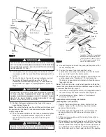
Page 5: ... Grilles Installation of Discharge Air Grilles See Figures 9 10 and 11 1 Refer to Adjustable Discharge Grilles Custom Air Flow Patterns page 6 of this instruction sheet to determine desired air flow direction 2 Place the two discharge grilles onto a flat surface in the desired configuration with tabs on each end of grilles upward 3 Fit the two louver guides over the two discharge grilles as shown ...

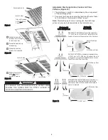
Page 6: ...ing 1 1 1 1 1 Louver Guide Louver Guide Discharge Grille 2 Louver Guides Tabs on Discharge Grilles Must Face Upward F Fi ig gu ur re e 9 9 D Di is sc ch ha ar rg ge e A Ai ir r G Gr ri il ll le e A Ar rr ra an ng ge em me en nt t C Cu us st to om m A Ai ir r F Fl lo ow w P Pa at tt te er rn n NARROW AIR PATTERN for high ceiling applications 11 3352 mm to 14 4267 mm concentrates the heated air to e...

Page 7: ... remove and discard blue jumper wire between L1 L3 Figure 13 7 F Fi ig gu ur re e 1 13 3 E El le ec ct tr ri ic ca al l W Wi ir ri in ng g Blue Optional Field Installed Wall Thermostat SPST or Internal CDFT Thermostat Accessory Optional Field Installed Wall Thermostat SPST or Internal CDFT Thermostat Accessory Optional Field Installed Wall Thermostat SPST or Internal CDFT Thermostat Accessory Whit...

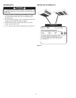
Page 8: ... cloth 4 Turn on the main line switch to restore power to the heater IMPORTANT INFORMATION TO PREVENT ELECTRICAL SHOCK DISCONNECT ALL POWER TO HEATER AT MAIN SERVICE PANEL BEFORE SERVICING 8 MODEL NO 557 DATE CODE 1195 CEILING HEATER FAN DECK BÀTI DU VENTILATEUR APPAREIL DE PLAFOND VOLTS WATTS AMPS 277VAC 5000 18 1 FOR SUPPLY CONNECTIONS USE NO 10AWG OR LARGER WIRES SUITABLE FOR 90 C MIN UTILISER ...

Page 9: ... 2059 001 1215 2059 001 1215 2059 001 2 Surface Ref Part Number for Models No Description CDF552SE CDF547SE CDF548SE CDF557SE CDF558SE Qty Repair Parts List for Ceiling Mounted Fan Forced Heaters 1 Element 302012813 302012803 302012801 302012814 302012812 2 2 Fan Delay 1414 2039 000 1414 2039 000 1414 2039 000 1414 2039 000 1414 2039 000 1 3 Fan Blade 1210 2000 000 1210 2000 000 1210 2000 000 1210...

Page 10: ...d Products THE ABOVE WARRANTIES ARE IN LIEU OF ALL OTHER WARRANTIES EXPRESSED OR IMPLIED AND ALL IMPLIED WARRANTIES OF MERCHANTABILITY AND FITNESS FOR A PARTICULAR PURPOSE WHICH EXCEED THE AFORESAID EXPRESSED WARRANTIES ARE HEREBY DISCLAIMED AND EXCLUDED FROM THIS AGREEMENT MARLEY ENGINEERED PRODUCTS SHALL NOT BE LIABLE FOR CONSEQUENTIAL DAMAGES ARISING WITH RESPECT TO THE PRODUCT WHETHER BASED UP...

Page 11: ...so o entramado que pueda soportar el peso del calentador 20 4 kg 45 lb El calentador se puede caer si no se cumple con lo anterior 10 No utilice el calentador si la rejilla de la salida no está insta lada Cuando instale rejillas con guías de rejilla asegúrese que las guías queden fijas en posición para que no puedan deslizarse y soltarse durante el uso de la unidad Instrucciones de instalación ope...

Page 12: ...acuerdo con la Hoja de Instrucciones suministrada con el control 9 Para conectar el calentador reducir el vataje o convertir de voltaje monofásico a trifásico consulte Conversión en el campo para una menor capacidad de vatios o Conversión para una instalación trifásica en la página 17 y en los diagramas de cableado Figura 13 página 17 10 Coloque la sección del calentador sobre los pasadores de la ...

Page 13: ... insertada antes de colocar la placa frontal sobre la sección del calentador Oprima e inserte la Espiga de pulgar después de que la placa frontal esté firmemente sellada contra la sección del calentador Tornillo 4 Placa frontal empotrada Sección del calentador Tuerca 4 Caja de montaje empotrado Tornillo 3 Espiga de pulgar 2 Agujero para espiga de pulgar 2 Pasador 4 Tornillo de conexión a tierra Ag...

Page 14: ...gar deseado para el calentador 14 Coloque el calentador en la cuadrícula de barras T Figura 4 y sujételo según sea necesario 15 Pase el cable de suministro eléctrico a través del conector y deje aproximadamente 203 mm 8 pulg de conductor dentro de la caja de montaje empotrado El cable de suministro eléctrico debe ser de tamaño No 10 AWG como mínimo con capacidad de 90 C como mínimo 16 Conecte el c...

Page 15: ...léctrico 13 Presione la sección del calentador sobre los pasadores y apriete bien las cuatro 4 tuercas extraídas en el paso 4 en los pasadores para asegurar la sección del calentador en la caja de montaje empotrado Figura 9 14 Conecte el conductor de tierra al tornillo verde de conexión a tierra en la caja de montaje empotrado 15 Coloque la placa frontal empotrada sobre la sección del calentador y...

Page 16: ...e Instalación de las rejillas del aire de descarga AVISO El área de la rejilla de descarga es rectangular las rejil las de descarga sólo pueden instalarse paralelas a las rejillas de admisión PARAIMPEDIRQUELASGUÍASDELASREJILLASDEDESCARGA SE CAIGAN ÉSTAS DEBEN ENCAJARSE FIJARSE EN POSICIÓN COMO SE MUESTRA EN LA FIGURA 12 16 Rejilla de descarga 2 Guías de rejilla Las pestañas de las rejillas de desc...

Page 17: ...o a trifásico retire y deseche el con ductor azul de puente entre L1 y L3 Vea la Figura 13 17 F Fi ig gu ur ra a 1 13 3 D Di ia ag gr ra am ma a d de e C Ca ab bl le ea ad do o Azul Termóstato unipolar opcional de la instalación del campo o termóstato interno 2YU46 auxiliar Termóstato unipolar opcional de la instalación del campo o termóstato interno 2YU46 auxil iar Termóstato unipolar opcional de...

Page 18: ...n el interruptor principal de la línea de suministro para restablecer la ali mentación eléctrica para el calentador INFORMACIÓN IMPORTANTE PARA EVITAR EL RIESGO DE CHOQUE ELÉCTRICO DESCONECTE TODA LA ALIMENTACIÓN ELÉCTRICA PARA EL CALENTADOR EN EL PANEL PRINCIPAL DE SERVICIO ANTES DE HACER CUALQUIER TRABAJO DE MANTENIMIENTO 18 MODELO NO 557 CODIGO DE FECHA 1195 PLATAFORMA DE VENTILADOR DE CALENTAD...

Page 19: ...salida 2501 2020 001 2501 2020 001 2501 2020 001 2501 2020 001 2501 2020 001 2 8 Guías de rejilla 1215 2059 001 1215 2059 001 1215 2059 001 1215 2059 001 1215 2059 001 2 En superficie No de Número de Parte para Modelos Ref Descripción CDF552SE CDF547SE CDF548SE CDF557SE CDF558SE Cant 1 Elemento 302012813 302012803 302012801 302012814 302012812 2 2 Retardo del 1414 2039 000 1414 2039 000 1414 2039 ...

Page 20: ... LA PRESENTE SE DECLINA Y EXCLUYE DE ESTE ACUERDO TODA GARANTÍA IMPLÍCITA DE COMERCIABILIDAD Y ADECUACIÓN A UN PROPÓSITO PARTICULAR QUE EXCEDA LAS GARANTÍAS EXPRESAS ANTEDICHAS MARLEY ENGINEERED PRODUCTS NO SE HARÁ RESPONSABLE POR DAÑOS CONSIGUIENTES QUE SE PRODUZCAN CON RESPECTO AL PRODUCTO EN BASE YA SEA A NEGLIGENCIA AGRAVIO RESPONSABILIDAD ESTRICTA O CONTRATO Algunos estados o jurisdicciones n...

Page 21: ...e installée de façon sécuri taire au plafond ou dans un cadre pouvant supporter le radi ateur 20 4 kg 45 lb Sinon le radiateur pourrait tomber 10 Ne pas utiliser le radiateur sans avoir installé ses grilles de sortie Lors de l installation des grilles avec guides de lame s assurer que les guides tombent en position afin qu ils ne glissent pas durant l utilisation Instructions d installation d util...

Page 22: ...allée avec la commande 9 Pour câbler le radiateur réduire la puissance ou convertir d une tension monophasée à une tension tri phasée consul ter Conversion sur le site à une puissance plus basse ou Conversion pour une installation 3 ø à la page 27 et le schéma de câblage Figure 13 page 27 10 Placer la partie radiateur par dessus les goujons sur la plaque d applique Figure 2 REMARQUE L extrémité de...

Page 23: ...nt 6 Installer les commandes en option si requises sur la partie radiateur en suivant la feuille d instructions emballée avec la commande 23 Écrou 4 Vis et boulons non fournis Vis 4 Trou de tige poussoir 2 S assurer que la tige poussoir est tirée avant de placer l enveloppe d applique sur la partie radiateur Appuyer sur la tige poussoir une fois l enveloppe d applique instal lée de façon étanche c...

Page 24: ...e d encastrement 17 Une fois le câblage complété remettre en place et fixer solidement le côté de la boîte d encastrement enlevé à l é tape 3 18 Installer les grilles d évacuation d air Consulter la section Installation des grilles d évacuation d air à la page 26 Installation de radiateurs encastrés dans des pla fonds permanents voir les Figures 5 6 7 et 8 1 Déterminer l emplacement du radiateur V...

Page 25: ...ont dans les trous de la partie radiateur 16 Alors que la plaque d encastrement est fermement logée contre la partie radiateur appuyer sur les tiges poussoir Ceci déploie les tiges poussoir et maintient temporaire ment la plaque d encastrement en position REMARQUE Les tiges poussoir aident à placer et maintenir la plaque d encas trement pendant l installation Un support sup plémentaire est requis ...

Page 26: ...N COMME L ILLUSTRE LA FIGURE 12 26 Grille d évacuation 2 Guides de lame Les onglets sur la grille d é vacuation doivent pointer vers le haut F Fi ig gu ur re e 9 9 1 2 3 Faire glisser la grille dans l ouverture suffisamment loin pour dégager les extrémités de la lame Pousser la grille vers le haut dans l ouverture Faire glisser la grille en position dans l ouverture 1 2 3 F Fi ig gu ur re e 1 10 0...

Page 27: ...pour une installation 3 Ø Le radiateur est câblé en usine pour une connexion 1 Ø seule ment Pour convertir à 3 Ø enlever et jeter le cavalier bleu entre L1 et L3 Voir la Figure 13 27 F Fi ig gu ur re e 1 13 3 D Di ia ag gr ra am ma a d de e C Ca ab bl le ea ad do o Bleu Blanc Noir Blanc Noir Noir Noir Noir Noir Noir Bleu Rouge Bloc d alimenta tion Limite supérieure Contacteur Noir Temporisation de...

Page 28: ...ière 4 Remettre le courant au niveau de l interrupteur principal pour rétablir l alimentation électrique vers le radiateur INFORMATION IMPORTANTE AFIN D ÉVITER UN RISQUE DE DÉCHARGE ÉLECTRIQUE COUPER TOUTE L ALIMENTATION DU RADIATEUR AU NIVEAU DU PANNEAU DE SERVICE PRINCIPAL AVANT D EFFECTUER L ENTRETIEN 28 MODÈLE No 557 CODE DE DATE 1195 PLATINE DE VENTILATEUR POUR RADIATEUR AU PLAFOND VOLTS WATT...

Page 29: ...8 0004 103 5018 0004 102 5018 0004 103 5018 0004 102 1 7 Grille de sortie 2501 2020 001 2501 2020 001 2501 2020 001 2501 2020 001 2501 2020 001 2 8 Guides de lame 1215 2059 001 1215 2059 001 1215 2059 001 1215 2059 001 1215 2059 001 2 En applique Nº de Numéro de pièce pour modèles réf Description CDF552SE CDF552SE CDF548SE CDF557SE CDF558SE Qté 1 Élément 302012813 302012803 302012801 302012814 302...

Page 30: ...VAUT SUR TOUTE AUTRE GARANTIE EXPRESSE OU IMPLICITE ET TOUTE GARANTIE IMPLICITE DE COM MERCIALISATION OU DE CONVENANCE À UN USAGE QUELCONQUE ALLANT AU DELÀ DE LA GARANTIE EXPRESSE CI DESSUS EST PAR LES PRÉSENTES RÉFUTÉE ET EXCLUE DE CETTE ENTENTE LA SOCIÉTÉ MARLEY ENGINEERED PRODUCTS NE PEUT SOUS AUCUNE CIRCONSTANCE ÊTRE RESPONSI BLE DE QUELQUE DOIMMAGE ACCESSOIRE ASSOCIÉ À CE PRODUIT SANS QU IL S...

Reviews: