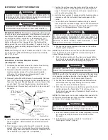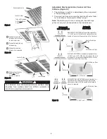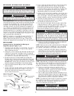
8. Position the heater section over the studs in the recess
mounting box (Figure 3).
NOTE:
The end of the heater section with the terminal block
must be posi tioned at the end of the recess mounting box where
the supply wiring enters.
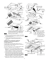
9. Push the heater section onto the studs and securely tighten
the four (4) nuts (removed from step 3) on the studs to
secure the heater section to the recess mounting plate
(Figure 3).
NOTE:
Insure that the “thumb pin” in each end of the discharge
grille opening is pulled outward to allow the body of the thumb
pins to fit into the holes in the heater section (Figure 3).
10. Position the recess face plate over the heater
section/recess mounting box, making sure that the thumb
pins are in the holes in the heater section.
11. With the recess face plate seated firmly against the heater
section, depress the “thumb pins”. This will cause the
thumb pins to expand and will temporarily hold the recess
face plate in place.
NOTE:
The thumb pins are an aid to help position and hold the
recess face plate during installation. Additional support (Step 12)
is required.
12. Install and securely tighten four screws (supplied) to secure
the recess face plate to the heater section (Figure 3).
13. Determine the desired location of the heater.
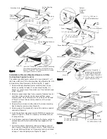
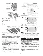
14. Position the heater in the T-bar grid (Figure 4) and secure
as required.
15. Run the power supply cable through the connector, leaving
about 8” (203 mm) of wire inside the recess mounting box.
(Power supply cable must be #10 AWG min. rated
90°C minimum.)
16. Connect the ground wire to the green ground screw on the
recess mounting box.
17. After wiring is complete, replace and secure the side of the
recess mount ing box previously removed in Step 3.
18. Install discharge air grilles. Refer to “Installation of
Discharge Air Grilles”, page 6.
Installation of Recess Mounted Heaters in Permanent
Ceiling (See Figures 5, 6, 7 and 8)
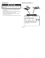
1. Determine the desired location of the heater. See Warning
No. 4 for minimum mounting clearance and Warning No. 9,
page 1.
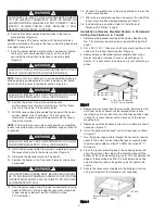
2. Cut a 22
1
⁄
4
” x 22
1
⁄
4
” (565 mm x 565 mm) mounting hole in the
ceiling for the recess mounting box (Figure 5).
3. Remove Recess Mounted Heater assembly from carton.
Heater assembly includes (1) recess mounting box, (1)
heater, (1) recess mount face plate and (1) set of discharge
grilles.
4. Remove recess mount box from assembly. Remove four (4)
nuts from studs so heater can be removed from recess
mounting box. Do not discard nuts since these will be used
in Step 13 to mount heater section back on to the recess
mounting box.
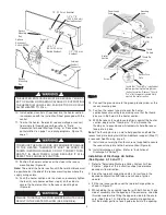
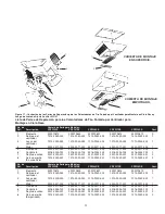
5. Remove one of the knockouts and install a cable or conduit
connector (Figure 7).
6. Install the optional disconnect switch (if required) as shown
in Figure 7.
7. Run the power supply cable through the connector, leaving
about 8” (203 mm) of wire inside the recess mounting box.
(Power supply cable must be #10 AWG min. rated 90°C
minimum.)
8. Place the recess mounting box in the ceiling opening and
align the marks on the sides of the mounting box with the
bottom of the finished ceiling (Figure 6). This will position the
edge of the mounting box 3/8” (9.5 mm) below the ceiling
and will allow the recess face plate to lay flat against the
ceiling.
9. Secure the recess mounting box to the building structure
using a mini mum of four fasteners (not supplied).
THE HEATER ENCLOSURE MUST BE SECURELY MOUNT-
ED TO CEILING OR FRAMING CAPABLE OF SUPPORTING
THE HEATER (45 LBS/20.4 KG). FAILURE TO DO SO COULD
ALLOW HEATER TO FALL.
TO REDUCE THE RISK OF FIRE OR PERMANENT DAMAGE
TO THE HEATER, THERMOSTAT MUST BE WIRED AS
SHOWN IN WIRING DIAGRAM. DO NOT CONNECT THER-
MOSTAT IN MAIN POWER LINES BECAUSE IT WILL
DEFEAT THE FAN DELAY FUNCTION.
FAILURE TO INSTALL THE FOUR MOUNTING NUTS COULD
RESULT IN THE HEATER FALLING (SEE FIGURE 3).
FAILURE TO INSTALL THE FOUR SCREWS COULD ALLOW
THE SURFACE WRAPPER TO FALL (SEE FIGURE 3).
FAILURE TO INSTALL THE FOUR SCREWS COULD ALLOW
THE SURFACE WRAPPER TO FALL (SEE FIGURE 3).
4
22
1
/
4
”
(565 mm)
22
1
/
4
”
(565 mm)
12” (305 mm) Min. 4 kW
24” (609 mm) Min. 5 kW
12”
(305 mm)
Min. 4 kW
24”
(609 mm)
Min. 5 kW
Wall
Wall
8’ (2438 mm) to Floor Min.
14’ (4267 mm) to Floor Max.
F
Fiig
gu
urre
e 5
5
Recess Mounting
Box
3/8”
(9.5 mm)
Wall
Wall
F
Fiig
gu
urre
e 6
6


