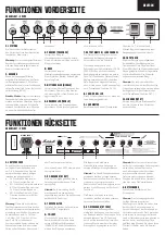
1. POWER
This is the on/off switch for the mains
power to the amp. When power is
switched on, the switch will light red.
Warning:
please ensure that the
amp is switched off and unplugged
from the mains electricity supply
before being moved.
2. OUTPUT
The output power is in low power
mode (5W) when set to low, when in
the middle position it is set to standby
and when set to high power the unit
runs at full power (20W).
Standby mode:
This should be used
during breaks in performances, instead
of leaving the amp on full power. Always
turn the power on for two minutes
before using the standby switch.
3. PRESENCE
Adjusts the high frequencies of the
power amp. Increasing the high
frequencies adds more bite to your
sound.
4. BASS
Adjusts the low frequencies of the
amp. It will add bottom end and
depth to your sound.
5. MIDDLE
Adjusts the mid frequencies of the
amp. Giving you anything from a fat
and full sound to an aggressive tone.
6. TREBLE
Adjusts the upper frequencies of the
amp. Your tone will get brighter as it
is turned up.
7. OUTPUT MASTER / LEAD CHANNEL
The output master control adjusts
the output of the preamp section to
the power stage.
The lead channel is selected
using the footswitch (supplied
PEDL-90003). The channel can
also be switched by using the push/
pull function of the output master
control. The amount of gain applied
to the lead channel can be controlled
using the input gain control.
8. LEAD CHANNEL LED
The LED indicator will light red when
the lead channel is selected.
9. LEAD MASTER
When the lead channel is active
the lead master control adjusts its
output level.
10. INPUT GAIN
Adjusts the overall sensitivity of
the input circuit. It controls the gain
level of the clean/crunch rhythm clip
mode and the lead channel. The pull
switch activates rhythm clip mode,
providing heavier, more driven tones.
Note:
the apparent drop in volume
when rhythm clip mode is selected
may be overcome by increasing the
level of the output master.
11. INPUT
Use this jack socket to connect your
guitar to the amp.
EXAMPLE SHOWN: 2525C
EXAMPLE SHOWN: 2525C
ENGLISH
11
8
9
10
7
6
5
4
3
2
1
FRONT PANEL FUNCTIONS
REAR PANEL FUNCTIONS
1. LOUDSPEAKERS
There are five speaker outputs
available. These are 1/4” jack
sockets. They are labelled according
to the intended impedances:
• 16Ω: connect a 16 Ohm guitar
cabinet to this jack.
• 8Ω: connect a single 8 Ohm guitar
cabinet or two 16 Ohm cabinets.
• 4Ω: connect a single 4 Ohm guitar
cabinet or two 8 Ohm guitar
cabinets.
Warning
:
although the amplifier has
five speaker outputs, never attempt
to connect more speakers than
rated. The safe combinations are: 1
x 16 Ohm, 1 x 8 Ohm, 1 x 4 Ohm, 2
x16 Ohm or 2 x 8 Ohm. Any other
speaker configuration may stress
the power amplifier section and in
extreme cases may lead to valve and/
or output transformer failure.
Never use the 2525 without a
speaker load.
2. DI OUTPUT
A DI output allows you to connect to
a recording device or sound desk.
Note:
using the DI does not omit the
need for a speaker to be connected.
See the warning on rear panel
function 1.
3. FOOTSWITCH
Connect the channel footswitch here
(PEDL-90003, supplied).
4. FX LOOP
The series FX loop connects the
amp to external FX (nominal level
-10dBV). The send jack socket
connects to the input of the external
FX unit and the return jack socket
connects to the output of the
external FX unit.
Note:
the send jack socket can be
used to connect to an external power
amp. This does not omit the need
for a speaker to be connected to
the amplifier’s output stage. See the
warning on rear panel function 1.
The return can be used to connect
an external preamp.
5. HT FUSE
The panel mounted fuse holder
allows access to replace a blown
fuse. If necessary the HT fuse will
blow to protect the internal circuitry.
This can sometimes happen in the
event of output valve failure.
Note:
replace the fuse only with
the value shown on the rear panel.
Before attempting to change the
fuse you must always first switch the
amp off and disconnect it from the
mains electricity supply. If in doubt,
contact your Marshall dealer.
6. MAINS INPUT
Connects the amp to the mains
power supply.
Note:
the mains input socket has
an integrated fuse compartment.
Ensure that the value of a
replacement fuse matches the
labelling on the amp rear panel. You
must always first switch off and
disconnect from the mains electricity
supply before attempting to access
the fuse compartment. If in doubt,
contact your Marshall dealer.
RETURN
SEND
1 x 16 OHM
LOUDSPEAKERS
FX LOOP
1 x 8 OHM
2 x 16 OHM
1 x 4 OHM
2 x 8 OHM
FOOTSWITCH
D.I.
MAINS INPUT
HT FUSE
T315mAE250V
PANL-00372
Iss
A
230V ~ 50Hz
100 WATTS
FUSE
230V - T1AE250V
100-130V - T2AE250V
1
2
3
4
5
6


