MIDI Mapping
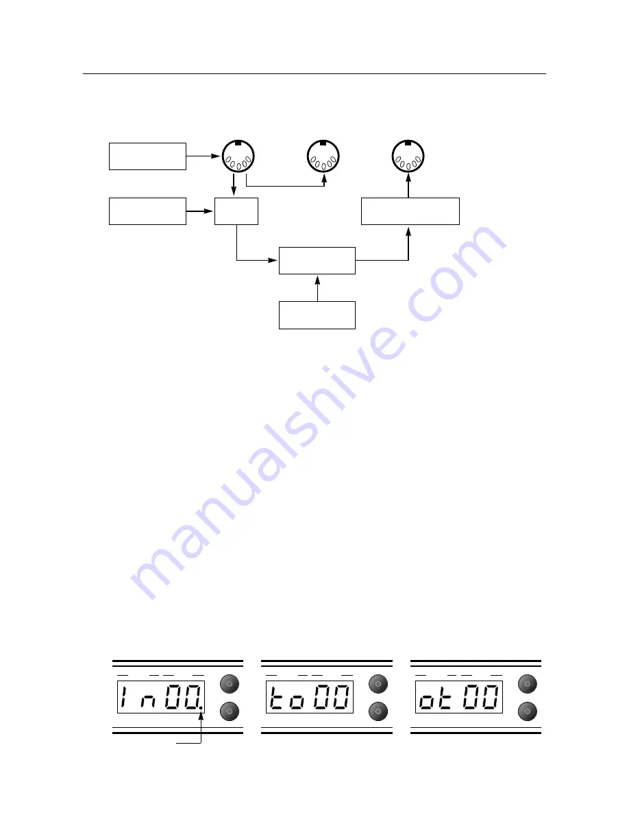
MIDI mapping is a simple and very useful facility, but it often confuses those who are new to MIDI. The MIDI
Mapping table is stored in the memory and is made up of two parts, Input mapping and Output mapping.
Input Mapping
The input mapping table makes it possible to transpose any incoming MIDI Program Change number to
select any desired JMP-1 patch. For Example:
MIDI Program Change 124 could be mapped to JMP-1 patch 36, so whenever the JMP-1 received MIDI
Program Change 124 it would call up patch 36. The Input mapping function is invaluable if you are using
a MIDI foot controller that sends fixed Program Change messages.
Output Mapping
In the same nature as input mapping, the output mapping function can transpose any outgoing Program
Change message. If the MIDI OUT of the JMP-1 is driving an external effects processor, the JMP-1’s output
mapping can be used to select a particular effects program for each JMP-1 patch, with the advantage that
several JMP-1 patches can share the same program on the effects processor.
To Edit The Mapping Table:
1)
Push Map key once to select incoming MIDI Program number. (See Fig 5). Use the data entry control to
select the incoming Program number (00 to 127). The decimal point signifies program numbers 100 and over.
2)
Push again to select the Internal Patch to be called up (00 to 99) (See Fig 6).
3)
Push the Map key a third time to set the outgoing MIDI Program Change message to (00 to 127) (See Fig 7).
4)
Pushing the Map key a fourth time will store edits and return the JMP-1 to Patch mode.
Note:
The mapping table is remembered whilst the JMP-1 is not powered.
Fig 7. Outgoing MIDI program
Fig 5. Input Mapping
Fig 6. Internal Patch Number
9
Patch
Data
Patch
Store
Patch
Data
Patch
Store
Patch
Data
Patch
Store
Indicates 100-127
Incoming MIDI
Data
4 Way Footswitch
(Patches 1-4)
Call up Internal
Patch (00-99)
Front Panel
Control
Output Mapping
to MIDI Device 00-127
MIDI
IN
MIDI
THRU
MIDI
OUT
Input
Mapping


