background image

On-Screen Menu 

(continued)

Access the main menu by pushing the 

MENU

 button on the front panel of the monitor.

Main Menu and Navigation

12

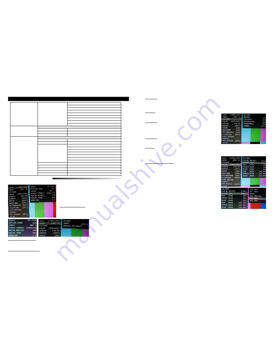
PICTURE SUBMENU

The Picture submenu allows the user to make adjustments to Brightness, Contrast, Saturation, Sharpness and 

Gamma using the Joystick control.

INFO SUBMENU

The INFO Submenu is a read-only display that gives the user 

information about the particular screen being viewed.  

No adjustment can be made from this submenu.

INPUT SUBMENU

The Input sub menu allows the user to select either the SDI-1 SDI-2 inputs or the Optional Input module if 

installed as the source to be displayed.

REMOTE

PIN 1 THRU 8

(Pin 5 is Ground)

R TALLY
G TALLY
B TALLY
LEFT R TALLY
LEFT G TALLY
LEFT B TALLY

RIGHT R TALLY
RIGHT G TALLY
RIGHT B TALLY

SDI STATUS

RETURN

ERROR COUNT

0 - 9999

RESET COUNTER
DISPLAY

OFF / ON / AUTO

SETUP

RETURN

FORMAT DISP

AUTO / ON / OFF

TIMECODE

OFF / LITC / VITC1 / VITC2

POWER SAVE

ALWAYS ON
2 MIN
5 MIN
10 MIN
30 MIN
1 HOUR
2 HOUR

KEY LOCK 

LOCK / UNLOCK

PICTURE DELAY

NORMAL / FAST / FASTEST

RESET TO MFG DEFAULT >

REST NOW / CANCEL

BACKUP USER CONFIG >

BACKUP NOW / CANCEL

RESTORE USER CONFIG

RESTORE NOW / CANCEL

• Step through menu items by pressing the 

é

ê

ç

 and 

è


   buttons.

• Choose a submenu or select a menu item by pushing the center  


MENU

 button. 

• Return to the previous menu by pressing the 

ç

 button.

• Exit the main menu by again pressing the 

ç

 button.. 

The Color submenu allows the user to access to the Color

management controls. 

■  

Color Matrix


Auto


• System automatically selects correct matrix.


• Typically, 601 for SD Formats, 709 for HD Formats.  


RGB


• User can manually set to RGB.


• RGB should be used with GBR422 systems.


601


• Conforms to ITU-R BT.601 matrix.


709


• Conforms to ITU-R BT.709 matrix.

■  

Color Temp


Use this setting to choose between color temperature presets:


• D65 (6500K). Conforms to CIE D65 White Point. x = 0.3127, y = 0.3290


• D93 (9300K). Conforms to Japanese D93 White Point. x = 0.2830 y = 0.2980


• USER (Adjustable Color Bias and Gain)


• CAL D65/D93


• CAL D65


• CAL D93

■  

RGB Bias and Gain

Select this submenu to fine-tune the monitor’s color balance (R, G, B). This should only be done by someone experi

-

enced with video engineering, as this will alter the overall color shading of the screen. The purpose is to allow color 

matching to other types of monitors and/or displays. Note: The Color Temperature preset will automatically switch to 

CUSTOM when Color Bias or Gain settings are adjusted. It is normal for color bias adjustments to be very subtle.

When selecting the RGB Bias and Gain submenus, changes to Gain and Bias will be seen in real time.  Once the 

proper level is achieved the user must save this setting by pressing the Joystick.  If the user leaves the setting 

menu before saving the value will return to the original setting.

Contrast


  • Varies between 0 and 100 (80 is standard).


  • 80 is default value with 100% gain of video signal.

Saturation


  • Varies between 0 and 100 (50 is standard).


  • 50 is default value with nominal color saturation.


  • Setting to 0 should display as monochrome.


  • Increasing value will increase color saturation.

Sharpness


  • Varies between 0 and 100 (0 is standard).


  • 0 is default value with no scaling artifact.

Gamma


  • Varies between 1.0 and 3.0 with 0.1 steps.


  • If White Balance is set to User Mode, changing gamma will have no effect.

COLOR SUBMENU

Brightness


  • Varies between 0 and 100 (50 is standard).


  • 50 is default value with standard black level.


  • Increasing brightness level allows user to see BTB (Blacker-than-Black).

13

Use this to perform “One Button Color Calibration of both D-65 and D-93 LUTs using the optional OR-SM and Minolta CA-210 color probe.

Use this to perform “One Button Color Calibration of D-65 LUT using the optional OR-SM and Minolta CA-210 color probe.
Use this to perform “One Button Color Calibration of D-93 LUT using the optional OR-SM and Minolta CA-210 color probe.

Summary of Contents for ORCHID OR-701A

Page 1: ...OR 701A 7 0 Full Featured Rack Mount Audio Video Monitor System Operating Instructions Marshall Electronics ...

Page 2: ...eeds The OR 701A is equipped with two HD SD SDI inputs with an active switched loop thru as well as optional input slot which can be used for and additional Component DVI I or other input formats Diagnostic tools include our exclusive ClipGuide feature 16 Tri ColorAudio Bar Graph meters with peak hold and numeric display of headroom and peak levels as well as real time analysis of color space conv...

Page 3: ...ne 3 5mm On the rear panel there is a stereo 4 line output using 3 pin XLR connectors and a 3 5mm 10 unbalanced jack to feed an external amplifier It is possible to utilize both the front panel Headphone Connectors and rear panel line output connectors simultaneously with individual volume controls Precision Audio Level Meters De embeds and displays up to 16 channels of audio using sixteen 64 segm...

Page 4: ...he push button at the bottom mutes the front speakers only When muted the led indicator turns RED Insertion of a headphone plug into either the or 3 5mm headphone jacks will not mute the front speakers The Front speakers are not affected by the Audio Mute command found in the Function Preset menu 1 2 3 4 5 6 Front Panel Features 6 1 4 5 6 3 2 7 7 Rear Panel Features Parallel Remote RJ 45 Pin Assig...

Page 5: ...ibrated setting GAMMA 1 0 to 3 0 in 0 1 steps 2 2 is Calibrated Setting COLOR RETURN COLOR MATRIX AUTO RGB BT 601 BT 709 COLOR TEMP CIE D65 JP D93 USER CAL D65 D93 CAL D65 CAL D93 RED BIAS 128 to 127 0 is Calibrated Setting GREEN BIAS 128 to 127 0 is Calibrated Setting BLUE BIAS 128 to 127 0 is Calibrated Setting RED GAIN 0 500 to 1 992 x1 00 is Calibrated setting GREEN GAIN 0 500 to 1 992 x1 00 i...

Page 6: ...ROMA C CHROMA C ON MONO Y C Y C ON MONO DISPLAY TYPE ZEBRA FILL Y UPPER LIMIT 100 0 IRE 7 3 to 109 1 Y LOWER LIMIT 0 0 IRE 7 3 to 109 1 C UPPER LIMIT 0 255 016 7 5 IRE 235 100 IRE C LOWER LIMIT 0 255 016 7 5 IRE 235 100 IRE USER ASSIGN RETURN F 1 THRU F 5 INPUT 1 INPUT 2 INPUT 3 GAMMA 1 0 GAMMA 1 8 GAMMA 2 0 GAMMA 2 2 GAMMA 2 4 GAMMA 2 6 WHITEBALANCE D65 WHITEBALANCE D93 MONO On Screen Menu contin...

Page 7: ...rms to CIE D65 White Point x 0 3127 y 0 3290 D93 9300K Conforms to Japanese D93 White Point x 0 2830 y 0 2980 USER Adjustable Color Bias and Gain CAL D65 D93 CAL D65 CAL D93 RGB Bias and Gain Select this submenu to fine tune the monitor s color balance R G B This should only be done by someone experi enced with video engineering as this will alter the overall color shading of the screen The purpos...

Page 8: ...e with 16 9 source or native 4 3 in AUTO mode H V Delay Use this setting to enable H V Delay In H V Delay mode both horizontal sync and vertical sync are delayed resulting in both horizontal and vertical blanking periods being shown at the center of the screen Shift H Use the Up éand Down ê menu buttons to change the value of this setting will shift the picture Horizontally Negative values will mo...

Page 9: ...no feed Load CH Preset From Use this menu to recall one of the 8 possible memory locations where the user previously stored channel output assignments Use of this Load command will override the current channel output assignments AUDIO CONFIGURATION SUBMENU 16 Save CH Preset To Use this menu to select which one of 8 memory locations where the user wants to store the current channel output assignmen...

Page 10: ...r conditions are indicated by a solid fill In either Zebra or Fill mode Red is the indication for Luma and Yellow is the indication for Chroma Y Limits These values are shared with WFM settings Set luminance upper and lower limits to be monitored Limits are displayed in IRE unit Varies between 7 3 IRE and 109 1 IRE This value will be shown in WFM window as red line Any data exceeding these values ...

Page 11: ...cases the value of LTC and VITC1 will be identical to each other Power Save When enabled the monitor will go to sleep after a predefined time has passed when loss of picture occurs When a valid video format is detected the monitor will wake up from the sleep state Pressing any front panel keys will wake up the monitor In the sleep state all lights including the backlight and front key indicators a...

Page 12: ...ause electrostatic charge on the surface attracting dust particles Neutralize static electricity effects by using the recommended cleaning and polishing practice Color Calibration Procedure In order to perform color calibration an optional OR SM Service Module is required Allow both the unit you want to calibrate and the Minolta CA 210 to warm up for a minimum of 20 minutes Attach the CA 210 color...

Page 13: ...ns or modifications in design or construction void this warranty It is considered normal for a mini mal amount of pixels not to exceed three to fail on the periphery of the display active viewing area Marshall Electronics reserves the option to refuse service for display pixel failure if deemed unobtrusive to effective use of the monitor by our technicians No sales personnel of the seller or any o...

Reviews: