background image


4

 1.3 Controller 

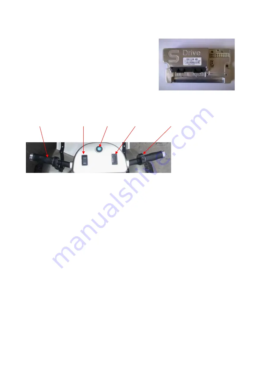
Controller is the main parts of the cart. Our cart use a 
PG24V/120A programmed controller. Setting the parameter to 
meet different guests. The controller has self-protect function For 
example, when there are troubles the controller can display work 
state on the light emitting diode. The users can diagnose and 
solve the troubles through the information displayed. 

(Photo3, controller)


1.4 the front parts 

Front parts contains speed bar, direction select switch, electric lock, electricity display, function bar. 


Speed bar   direction switch  electric lock  E-display     function bar 


1.5 Electric wiring harness 

All wiring harness consist of control wiring, front part wiring, light connected wiring and rear light wiring.


2. Function explain 

2.1 electric lock 

When the key turn at “OFF”, the car is parking. When the key turn to “.”( a red dot), indicating the car is power on. 
Then you can choose forward or reverse to drive the car.


2.2 Direction select switch


This switch is used to choose the direction when driving. FWD means forward; REV means reverse. 


2.3 Speed bar 

Using Hall speed bar, Counterclockwise rotation of the hand car Continuously Variable 


2.4 E-display 

The electricity capacity is displayed by ten LED lights, When only 1 and 2 LED shine means there is lack of 
power and need recharge.   


Summary of Contents for DG24800

Page 1: ...1 DG24800 Manual...

Page 2: ...2 contents 1 Electrical system summarize 3 2 Function explain 4 3 Daily maintenance 6 4 General trouble service 10 Appendix 1 Trouble diagnose chart 12...

Page 3: ...ing Please charge the battery full before using the cart in right way 1 1 Battery The battery is in series by two DJM12V45AH lead acid battery and supply the power DC24V to the cart the batteries are...

Page 4: ...ch electric lock E display function bar 1 5 Electric wiring harness All wiring harness consist of control wiring front part wiring light connected wiring and rear light wiring 2 Function explain 2 1 e...

Page 5: ...hould move the cap of the socket up insert the tie in into the socket and connect the other end with the power supply When the red light on means the charger is work when the green light on means it i...

Page 6: ...urface on a certain time ensure the battery connect well and check the terminal protect jacket if loose from the electrode check 1 time per half a year 4 The usage of the battery can not excess deep d...

Page 7: ...remove the controller surface of the dust and rust particularly corrosive substances so as not to cause the electronic control failure It is strictly prohibited to use the controller in wet overload...

Page 8: ...ntroller to repair or change it otherwise the motor and rear axle may damaged 2 There is no repairable parts on motor and rear axle itself for the user so please do not try to open the controller to r...

Page 9: ...ct position backward and lean on down fasten the 2 tighten bolts 4 Install all parts by the opposite sequence as disassemble 3 6 Replace the front light bulb 1 Turn off the ignition key switch 2 Loose...

Page 10: ...can not be linked to the mobility to long usually less than 20 hours 1 Charger can only be used for DG24800 series of electric car can t be used as the other power 2 The input voltage of the charger...

Page 11: ...g if it s the battery connecting wire not firm and connector is not good contacts Check the voltage of the charger socket 1 and 2 Normally is 24V or it is the connection wires problem Fault phenomena...

Page 12: ...perating with charger attached 3 Intermittent battery connection 2 1 MAIN OFF FAULT main contactor driver Off fault 1 Main contactor driver failed open 2 3 MAIN CONT FLTS main contactor fault 1 Main c...

Page 13: ...not correspond tothrottle request 2 Short in motor or in motor wiring 3 Controller failure 4 3 EEPROM FAULT EEPROM fault 1 EEPROM failure or fault 4 4 POWER SECTION FAULT power section fault 1 EEPROM...

Reviews:

Related manuals for DG24800