background image

AS Martem                                              Data Concentrator TELEM-GW6  User Manual 


Akadeemia tee 21G                         Tel: +372 639 79 79                             E-mail: martem@martem.eu 
12618 Tallinn                                  Fax: +379 639 79 80                                                 www.martem.eu 
Estonia 
 

- 11 - 

10.3.1 Ports Tab Card  
 
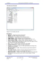
Ports/configuration tab card (Figure 10.3.1) is active when the GW6 
configuration window is opened. 
 
From the View menu a Basic or an Advanced view of the Port 
configuration tab card
 can be selected. The Advanced view shows the 
additional query and echo suppression parameters. 


Figure 10.3 .1 Configuration window with an advanced Port configuration tab 
card 
 
Configuration parameters of a port: 

  Protocol – Communication protocol used by all the devices of this port. 

Each protocol name is accompanied with a symbol l”^” or  ”

ν

 ” which 

indicates whether the port is used for an uplink or a downlink channel. For 
example, “Modbus 

ν

” means that this port is used for downlink with  

Modbus protocol. 

  Baud rate – Data communication rate  

  Parity – Use of parity bit for all the devices on this channel 

  Stop Bit – possible values are 1, 2 

  Data Bits – possible values are 7, 8 
Summary of Contents for TELEM-GW6

Page 1: ...Data Concentrator TELEM GW6 User Manual Martem AS 2010...

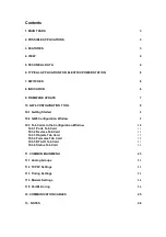
Page 2: ...ng Started 8 10 2 GW6 Configuration Window 9 10 3 Tab Cards in the Configuration Window 10 10 3 1 Ports Tab Card 11 10 3 2 Devices Tab Card 13 10 3 3 Objects Tab Card 15 10 3 4 Formulas Tab Card 19 10...

Page 3: ...aster unit functions in the substation secondary equipment system Duplex data communications between the feeder and the equipment level versus the station control level in substations using different...

Page 4: ...8 Tallinn Fax 379 639 79 80 www martem eu Estonia 4 4 View Figure 4 Telem GW6 view 5 Technical Data Data communication protocols To higher or lower level systems IEC 60870 5 101 or IEC 60870 5 104 To...

Page 5: ...ction with RJ45 optically isolated connector 1x RS 485 serial connection with RJ45 optically isolated connector 1x GPS Fiber optic connection with Versalink connector Expansion card 2 8x RS 232 serial...

Page 6: ...T to ON state Alert indication LED starts blinking with 5 second interval 2 Switch DFT SET back to OFF state when the alert indication LED is blinking to apply default setup If DFT SET is switched bac...

Page 7: ...your computer 4 Insert the card to Telem GW6 SD Memory Card slot SD Memory Card slot is located at the back of the device 5 Perform reset operation to Telem GW6 device 6 Wait until the device resumes...

Page 8: ...rface window with the main menu is opened Figure 10 1 1 User interface window The following parameters are shown for information Port PC port which is used to communicate with GW6 Link address Link ad...

Page 9: ...6 Configuration Window To open the GW6 configuration window select Device GW6 RTA A from the user interface main menu Shortcut icons below the menu bar Open a new configuration Open a configuration fi...

Page 10: ...Tab Cards in the Configuration Window Configuration and setting parameters can be utilized by using topic tab cards Ports Devices Objects Formulas RTA IO Status A click on a tab card button switches b...

Page 11: ...he additional query and echo suppression parameters Figure 10 3 1 Configuration window with an advanced Port configuration tab card Configuration parameters of a port Protocol Communication protocol u...

Page 12: ...ice on uplink channels IEC ASDU Address ASDU address on uplink channels Length of the ASDU Address Length of the ASDU address in bytes on uplink channels Typically 2 possible values are 1 or 2 IEC Obj...

Page 13: ...in bytes possible values are 1 2 or 3 In use Indicates whether the device is in use or not If the device is not in use the whole row has a grey background Port Port no of GW6 to which the device is c...

Page 14: ...on the shortcut icon a new device with default settings is added It is also possible to add new devices with a right mouse click which makes the extended control menu to appear Add Devices dialog box...

Page 15: ...ing window always appears before removing operations are concluded Select Yes to accept or No to cancel the removal operation of the devices 10 3 3 Objects Tab Card Figure 10 3 3 Objects tab card The...

Page 16: ...ect and time marking mode can be selected Sub Type v Object s subtype for downlink The following dialog box opens on clicking Object type Format Time marking DI Digital input Single Double Without tim...

Page 17: ...e change in value is bigger than deadband 2 of full scale then a call to SCADA system is initiated Raw Min Raw Max Minimum and maximum raw values of analog measurement before scaling Scale Min Scale M...

Page 18: ...object status Used for objects which statuses are not received with General Interval time short circuit current etc Adding Objects By clicking on the button a new device with default settings is adde...

Page 19: ...Raw Max Scale Min Scale Max Forb Ports as in Objects Tab Card LED no The alarm LED number 1 16 on the LED Alarm panel which corresponds with the result of this formula DO addr Number of the digital o...

Page 20: ...priority of the operation Example sqrt 101 2 102 201 202 203 3 Operators Oper Obj type Description Sample Priority DI AI Addition 101 3 2 3 DI AI Subtraction 101 0 49 3 DI AI Multiplication 101 2 2 DI...

Page 21: ...mula row with default settings is added By clicking on the button the selected formula row is removed Formula rows can also be added removed or cleared by using the extended control menu like in the O...

Page 22: ...8 Tallinn Fax 379 639 79 80 www martem eu Estonia 22 10 3 6 Status Tab Card Figure 10 3 5 Status tab card Status tab card presents the status of GW6 general configuration parameters and transfer stati...

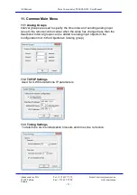
Page 23: ...groups are used to specify the time interval of sending analog input value to the remote control center when the value has changed less than the deadband Interval groups can be added to analog input o...

Page 24: ...ngs Configure modem settings for modem callout communication mode Port 2 11 5 Port Mirroring To determine 2 mirror groups 2 ports in each group In case of mirrored ports the data will be sent and rece...

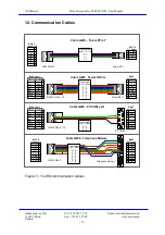
Page 25: ...xD GND 2 3 4 5 6 7 GND Signal RJ45 RTS CTS RxD TxD GND 2 3 4 5 6 7 Shield Pin Signal RJ45 1 8 RTS CTS RxD TxD GND 2 3 4 5 6 7 Pin Signal DB9F 1 8 PC COM 8 1 Port 1 Port 6 13 Pin RTS CTS RxD TxD GND 2...

Page 26: ...D SGND GND 7 TX RTS 8 DTR GPS if supported 13 Notes If not stated otherwise on the individual pages of this document AS Martem reserves the right to make modifications Although the contents of this pu...

Reviews: