All material © 2010 Martin Audio Ltd. Subject to change without notice
29
3.10.3.8
Power limiter
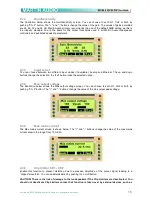
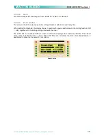
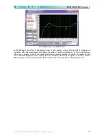
This menu controls the output power limiter which decreases the gain in order to reduce the power delivered
to the load. The amplifier measures the load current to estimate the actual active power output being
delivered. Given the low efficiency of electromechanical transducers (<10%), almost the same level of power
is transformed into heat in the driver voice coil. This limiter is intended to avoid burning the voice coils of the
drivers while exploiting their maximum performances.
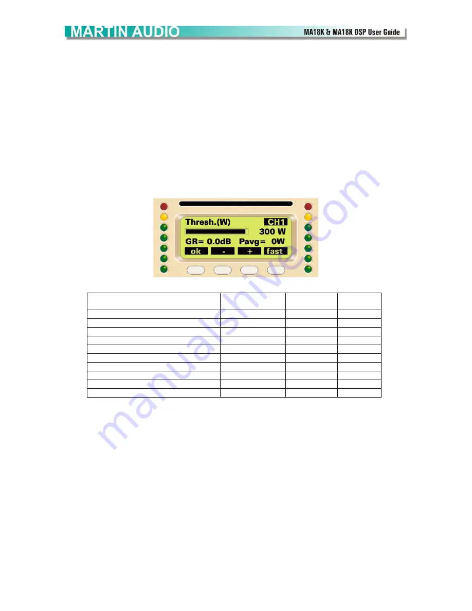
The parameters are the power threshold in W at which the gain begins to get reduced, the attack time, that is
the response time of the limiter intervention and the decay time, that is the time constant after which the gain
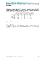
is restored to the nominal gain. You should select as power threshold the true power handling of your
speaker (it is usually between one third and one half of the declared RMS or AES power handling, see the
table below), with time constants related to the thermal inertia of your speaker (the mass to be heated). So,
huge 4” VC subwoofers could require some seconds of attack and some seconds of release time, while tiny
1’ VC tweeters may need less than 1/10 of second of attack time. When editing the threshold, the display
shows in real-time the gain reduction due to the combined peak/power limiting function (GR = xx.x dB) and
the power really delivered to the load (Pavg=xxxxW).
Power Limiter
DRIVER
POWER
THRESHOLD
ATTACK
TIME
DECAY
TIME
1” VC tweeter
10…20 W
100 ms
300 ms
1.5” VC tweeter
20…30 W
150 ms
300 ms
2” VC horn driver
20…40 W
200 ms
400 ms
3” VC horn driver
30…50 W
300 ms
500 ms
4” VC horn driver
40…60 W
500 ms
3000 ms
2” VC midrange
30…100 W
500 ms
3000 ms
3” VC midbass
50…150 W
1000 ms
5000 ms
4” VC woofer
100…200 W
2000 ms
5000 ms
4” VC subwoofer
150…300 W
4000 ms
8000 ms
6” VC massive subwoofer
250…500 W
6000 ms
10000 ms
Suggested power limiter settings for common used drivers.
The power limiter should be used to protect the drivers from burning, and at working levels it normally
shouldn’t activate. Check the gain reduction, it should not raise over 2-4 dB even during loud passages of
music, in order to obtain the optimal sound. Note that a normal musical signal has very loud peaks, but a low
average level, while a continuous tone has a much higher average power even if it has a modest impact on
the ear.
3.10.3.9
Advanced
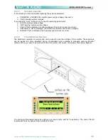
These are advanced settings that are not usually found on any other sound processor or amplifier;-
3.10.3.9.1 Damping Control
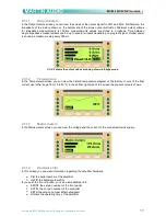
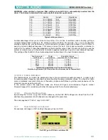
This unique and patented feature allows you to add a “virtual” resistor in series with the amplifier output. The
value of this resistor can also be negative in order to get the correct damping factor with any cabling you use.
For example, if you use a 10 meters cable for powering the subs, you will add a parasitic series resistance
(0.3 ohm for example). By enabling the damping control, you can add a negative resistance that
compensates the cable resistance.

