background image


U

Hub


USER


GUIDE


U

Hub


User


Guide


V1.0


13


…………


Audio


Connections


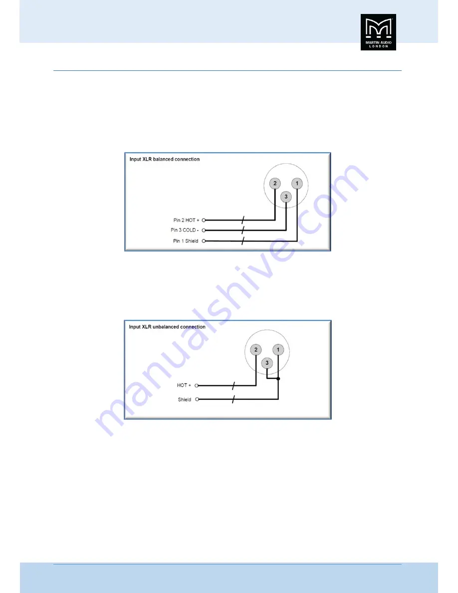
Input


Connections


For


each


audio


input


there


is


a


female


XLR


connector


for


analogue


or


AES


signals.


The


HOT,


+


or


‘in


phase’


connection


should


be


made


to


pin


2


of


the


XLR


connector.


The


COLD,

 ‐ 

or


‘out


of


phase’


connection


should


be


made


to


pin


3


of


the


XLR


connector.


Pin


1


of


the


XLR


connectors


is


internally


connected


to


the


chassis.


The


shield


of


the


input


cable


should


always


be


connected


Pin


1


of


the


XLR


to


ensure


that


EMC


performance


and


regulations


are


met.


Using


unbalanced


connections


Please


note


that


the


use


of


unbalanced


connections


is


not


recommended,


however


when


connecting


the


U

Hub


to


an


unbalanced


audio


source,


the


signal


conductor


should


be


connected


to


XLR


pin2.


The


‘Cold’


conductor


or


cable


screen


should


be


connected


to


XLR


pin


1


with


a


short


connection


made


between


pin


1


and


pin


3.


Summary of Contents for U-Hub

Page 1: ...User Guide U Hub Ethernet to U NET Bridge V1 0 Nov2018 ...

Page 2: ...MERS IN CANADA 6 Thanks and Unpacking 7 Unpacking the Martin Audio U Hub 7 INSTALLATION INSTRUCTIONS 7 Mechanical Installation 7 AC Power Connection 8 The User Guide 9 Introduction and Key Features 10 Introduction 10 Key Features 10 U Net Connections 10 Block Diagram 11 System Example 11 Audio Connections 13 Input Connections 13 Using unbalanced connections 13 U Hub Network Connections 14 Panel La...

Page 3: ... Net Splitter 19 Vu Net 20 Introduction 20 Menus 20 Window components 21 Working Offline 36 Device Discovery 36 Device ID 43 Right Click menu 44 IP Settings 45 Technical Specifications 47 General 47 Rear Panel 47 Front Panel 47 Physical 47 Technical Drawing 48 Warranty 49 ...

Page 4: ...ect the power cable from being walked on or pinched particularly at plugs convenience receptacles and the point where they exit from the apparatus 11 Only use attachments accessories specified by the manufacturer 12 Use only with the cart tripod bracket or table specified by the manufacturer or sold with the apparatus When a cart is used use caution when moving the cart apparatus combination to av...

Page 5: ...nt 12 Utilisez uniquement le chariot le trépied le support ou la table spécifiés par le fabricant ou vendu avec l appareil Quand un chariot est utilisé soyez prudent lorsque vous déplacez l ensemble chariot appareil afin d éviter toute blessure en cas de chute 13 Débranchez cet appareil pendant les orages ou lorsqu il n est pas utilisé pendant de longues périodes de temps 14 Adressez vous à un per...

Page 6: ...should be open at the front and back to allow free ventilation and movement of air through the product DECLARATION OF CONFORMITY WITH FCC RULES We Martin Audio Ltd of Century Point Halifax Road Cressex Business Park High Wycombe HP12 3SL England declare under our sole responsibility that this family of devices complies with Part 15 of the FCC Rules Operation is subject to the following two conditi...

Page 7: ...teur d alimentation ou la borne de terre de l installation Le cordon doit être un maximum de 6 2m de long 14 AWG 2 5mm2 CSA être classé SJ SJT SJE ou 300 500V H05W F et être marquée VW 1 THIS PRODUCT IS DESIGNED FOR PERMANENT INSTALLATION It must be fitted in to a 19 rack enclosure and not operated unless so installed The rack enclosure should be open at the front and back to allow free ventilatio...

Page 8: ...on The U Hub is designed to be mounted in a standard 19 rack enclosure Where the processor is used in a fixed installation as long as the bottom unit is supported and there are no gaps between units it is acceptable to use only the front panel 19 rack holes when fitting it in a standard rack enclosure If the U Hub is mounted in a mobile rack it is important that the rear or sides are supported wit...

Page 9: ... ensure that dirt liquids and vapour from oil based theatrical smoke haze or fog machines is not ingested by the U Hub Damage so caused is not covered by the manufacturer s warranty AC Power Connection The U Hub utilises a standard IEC AC power connector fitted with a retaining clip Use only an AC power cable with a correctly wired IEC connector to make the connection to the mains power supply Thi...

Page 10: ...etailed explanation of the front and rear panel controls and indicators is contained in the next section The final section describes use of the U Hub within Martin Audio Vu Net software This is an abridged guide covering essential U Hub functionality for full details of Vu Net please refer to the Vu Net User guide which can be downloaded from the Martin Audio website ...

Page 11: ... well as supporting a simple to use redundant loop With U Hub an MLA Series system with onboard U NET can be seamlessly integrated into a TCP IP network and controlled via VU NET software When used in conjunction with the Martin Audio DX4 0 networked system controller U Hub can connect audio and network to an MLA Series system with a single cable via a Dante digital audio network U Net Connections...

Page 12: ...low continuous communication Audio connections are combined with the network feeds Audio input 1 is connected to a pair of spare connections in the U Net port 1 ODU This would usually be used as the send to the first array A return from the array would be connected to the first link in connection Audio 2 is combined with the second ODU in the linked pair allowing audio to be fed to a second array ...

Page 13: ... standard 3 pin XLR The XLR is connected to the audio input The audio is daisy chained between cabinets using standard audio link cables When the final network cable is routed back to the U Hub it is terminated using the first of the link pairs The link pairs link the network connections first two twisted pairs but NOT the audio meaning that the link out can be used to route a completely independe...

Page 14: ...f the XLR connectors is internally connected to the chassis The shield of the input cable should always be connected Pin 1 of the XLR to ensure that EMC performance and regulations are met Using unbalanced connections Please note that the use of unbalanced connections is not recommended however when connecting the U Hub to an unbalanced audio source the signal conductor should be connected to XLR ...

Page 15: ...ur Ethernet network There are two front panel mounted U Net ports for connection to the U Net enabled devices in your system These use ODU connectors to the LEMO high speed data series pattern Wiring configuration is as follows The two pairs of linked ODU connectors are wired as shown in the block diagram Pins 1 2 3 6 are linked together pins 4 and 5 on the link out connectors have the audio signa...

Page 16: ...D will illuminate green when a good connection is made to a U Net enabled device connected to port 1 5 U Net Connections Six ODU connectors provide U Net connectivity consisting of Port 1 port 2 and two linked pairs Port 1 and the Out connection of each linked pair also carry audio routed from the input connectors on the rear panel 6 U Net Status The U Net LED will illuminate green when a good con...

Page 17: ...Hz without re configuration The IEC connector should be compatible with the retention clip so it can be secured with the clip to ensure the connector cannot accidentally disconnect 2 Main Fuse This should be fitted with an anti surge T fuse rated at 1 amp 3 Ethernet Neutrik Ethercon allowing an ethernet connection using wither a standard CAT5E connector or an Ethercon cable 4 Analogue AES EBU Audi...

Page 18: ...sing the IP Reset switch on the front panel Press and hold the switch for approximately 3 seconds and the U Hub will be set to Static IP with an address of 169 254 19 71 The default address gives you the flexibility to connect to the U Hub without having to adjust your PC LAN settings if the PC is in dynamic mode it will self assign a link local address in the 169 254 xxx xxx domain If your networ...

Page 19: ...o the first subwoofer where the racks are in close proximity to the subs 15m PWA00063 General purpose cable often used to link from a U Hub to the first subwoofer in an array 35m PWA00040 Most commonly used as part of an array loom to go from a rack up to a flown array and back and as cross stage Ethernet links 50m PWA00077 Extra long Array looms 75m PWA00052 Supplied on a cable drum used for Ethe...

Page 20: ...ost CAT5E cable which would be a more cost effective solution for installed systems PWA00056 This is a 10m CAT5E cable terminated one end in an ODU connector and the other in an RJ45 connector As above this offers a cost effective solution for certain applications Audio U Net Splitter The U Hub audio integration features will allow audio and network signals to be fed to an array using a single cab...

Page 21: ...he Panasonic tablet PC supplied with MLA and MLA Compact systems It is an optional method of control for full use of MLA Mini DD12 PSX and CDD Live Menus Before we look at the design process that is used with a system it is worth taking a look at the file structure which we will refer back to throughout the chapter When you run Vu Net you will see the following Window This is a blank screen with o...

Page 22: ...u will notice that the top left of the main window has your project name and a number of options on the toolbar are now available Window components The window has a number of distinct sections with their own function Menu and Toolbar Along the top of the window is a standard file menu and tool bar which gives quick access to a number of functions File ...

Page 23: ...ou the opportunity to give the project a name and to choose a convenient file location As with Display 2 1 it is sensible practice to save the file in a folder dedicated to a specific event All subsequent Saves will overwrite the existing file As shown the keyboard shortcut Ctl S can be used to save a project It is a good idea to frequently save your work Vu Net files are saved with a vup file ext...

Page 24: ...s Preferences Preferences have some important options for how Vu Net operates Calculations The first option is labelled Calculations and allows you to select the venue temperature in steps of 5 This is used when the option is selected in the Merlin Controller to read delay figures as a distance as opposed to time The temperature adjustment calculates the delay time according to the speed of sound ...

Page 25: ... responds dynamically to objects selected can be displayed as a window on the application or as an Infopop Help includes a sub menu for accessing help from remote infocenters This is not currently operational and will be a future upgrade Master Overview There is an option within Master Overview to show the Merlin Controllers in the system in the Overview tab This is for systems where Merlins are u...

Page 26: ... appear listed in the bottom Available IP addresses You can set an IP address Filter in the smaller window which will search only for IP addresses within the range of values between the two entered which should be separated with a comma This could be used if you have two systems running on the same Ethernet network and need to control them independently Only devices with their IP address set to va...

Page 27: ...n functions within the application Increment Values These allow the default increment values for both Gain and Delay to be changed as required The default for Gain is 0 5dB but the options are for increments of 0 1 0 2 0 25 0 5 or 1dB For delay the default is 25ms the options are 0 1 0 2 0 25 0 5 or 1ms Windows Power Option Allows Vu Net to prevent Windows from implementing changes to the power se...

Page 28: ...is used to convert the amplifier modules used in MLA and MLD cabinets from one type to another Mechanically and electrically these are identical they simply need a firmware conversion so the system is aware of what type of enclosure they are powering An MLD module can be converted to an MLA or more commonly an MLA module to an MLD Window The Window menu is used to determine which sections of the p...

Page 29: ... ways 1 Click on Start using the software 2 Click on the x in the Welcome box in the top left of the window 3 Click on the drop down arrow in the top right of the window and select close Any of these will close the welcome screen to reveal the project window User Guide This is a link to this very guide slightly rearranged for use in the field when running the software The contents page features li...

Page 30: ...all selected components horizontally on the page The second aligns all selected objects vertically The third tool is used with the Merlin When a system is discovered its network connections are drawn in place The two U Net nodes on the Merlin usually run as a closed loop will go off to the first cabinet in the array and back from the last cabinet Depending on the layout of your system diagram this...

Page 31: ...ain mute and Delay and with a link to EQ functions This is designed to be used once a show is in progress to allow easy monitoring of an entire system from a single page The Master Overview is opened as another tab next to the Project System diagram and any other open arrays or components Ganging From version 2 1 Ganging for all devices is accessed from the toolbar using this button A list of all ...

Page 32: ...ction mutes every input and output on connected Merlins and every zone on all arrays Once used there is no global un mute all Merlins and arrays will have to be individually un muted Note that Show Modes does not change operation of the System Mute the confirmation window will always appear Our advice is never to leave a system muted within Vu Net always use a mute that can be defeated manually su...

Page 33: ... allowing you to reconnect to the project Project Workspace The workspace is divided into several sections which can each be opened closed or in the case of the ancillary section detached as a floating window By default the workspace appears like this There are three main sections the first is the system diagram ...

Page 34: ...edge of the other windows You can then drag either left or right to adjust the relative sixes of the windows Alternatively the white drop down arrow gives you the option to maximise the screen The other windows will not be closed they will be represented by an icon on the right side of the page with the option to restore Clicking restore will return the windows to their previous state On the right...

Page 35: ...hows all three options available Any of the three options can be viewed by clicking on the relevant button As with the Project window any of the selected options can be detached as a floating window maximised or closed by clicking on the white arrow If all options in the window are closed the project window will fill the space if that is also closed the Project window will fill the space The Prope...

Page 36: ...erties and gives the option to display or hide any of the properties in a particular category by clicking on the small arrow leaving just the category heading The third icon displays advanced properties for the selected element The final icon will reset any modified properties to their default values The Outline window displays a miniature thumbnail of the system diagram for whichever project is s...

Page 37: ... turned back on and the status of all parameters of every DSP We will show how to introduce all available elements into a project off line but will cover Device Discovery and on line operation in a later chapter Adding U Hub Adding any devices to a System diagram is a simple case of clicking on the required item in the Palette Then click on the System Diagram workspace The cursor will have a small...

Page 38: ...nternal Firmware database If it detects an older Firmware version you will see the following window For more detail on Firmware updates please see the full Vu Net User guide Finally it is possible you may see this window This would indicate a problem down stream of the U Hub are the cabinets powered Are all the network connections made Is a U Hub or Merlin set to Static IP instead of Dynamic Can y...

Page 39: ... shown at the top All devices connected to that U Net loop will be listed grouped by type Next press the Run Wizard button and an individual Wizard will run for all categories the first will be MLA MLD or MLA Compact If you have more than one array of each type of cabinet on the same U Net loop you have the opportunity to divide them into two or more arrays as required Use the up down button to se...

Page 40: ... you only have one array it is still worth flashing all LED s to see the look on the faces of the lighting technicians when they see LED lighting over which they have no control Next click the BY ONE button This will flash the LEDs in sequence from top to bottom As the U Net network is bi directional it is entirely possible that the arrays could have been discovered starting with what is actually ...

Page 41: ...owing window for any connected MLX or DSX By default the Arrangement will be displayed as Flown therefore the No of columns field will show 1 If you click on Flown it will toggle to Ground Stacked and if this is how your subs are deployed you can select the number of columns to reflect in Vu Net exactly how they are positioned This could even mean making the columns equal the number of enclosures ...

Page 42: ...rays it is essential to ensure that they are correct so delay and other parameters applied are directed to the correct cabinet At this stage you can also change the LED badge to flash on the rear They are configured for the front LED by default signified by the F on the thumbnails Double click directly on the badge and you will see the F become a B to signify the back LED This will flash instead o...

Page 43: ...ll not synchronise correctly on the first pass in which case there will be a Red Fail in the Result column for that device If this occurs wait until the rest of the synchronisation is finished and click on the Synchronise button for that device in the extreme right column The device will attempt a further synchronisation which should result in a success and a green OK A complete successful synchro...

Page 44: ... Finish and a further Finish on the Device Discovery Report window Repeat the procedure for all connected U Hubs or Merlins which will all have their own U Net ring of elements Once this is completed the Vu Net workspace will appear as shown Device ID In larger systems with multiple U Hubs it is helpful to identify them individually so they can be given an appropriate name Double clicking on the U...

Page 45: ...ocate Duplicates the identification function illuminating the front panel name on the Vu Net thumbnail and making the LEDs on the front panel of the U Hub flash Synchronise Repeats the synchronisation that Vu Net performs following device discovery Disconnect Reconnect This allows you to disconnect the U Hub from Vu Net and then reconnect IP Settings This opens the IP Configuration Window to selec...

Page 46: ...ngs By default the U Hub is set to dynamic IP so will require a Lan with DHCP present to assign an IP In a standard MLA system this is provided by the Zone Director housed in the Master rack The U Hub can be changed to Static IP for sophisticated networks which may be shared by many devices Right clicking and selecting IP Settings opens this window To change to Static IP click on Set IP address ma...

Page 47: ...is the same address that can be set using the front panel IP reset switch 169 254 19 71 This can be changed to any IP address within the range you require for your network Once the U Hub has been configured for Static IP the front panel Static IP LED will illuminate ...

Page 48: ...pe ETHERNET 1 x Neutrik Ethercon MAINS POWER 3 pin IEC with connector retaining clip FUSE User replaceable 1A T type 20mm Front Panel AUDIO OUT AND U NET 6 x ODU 8 pin connector ports Audio In 1 2 3 Out on ports 1 3 5 U NET STATUS Bi colour Green Red LED on U Net Ports IP RESET TO DYNAMIC Recessed push button ETHERNET CONNECTION Green LED Online MAINS POWER Red LED Mains power present Physical DIM...

Page 49: ...U Hub USER GUIDE U Hub User Guide V1 0 48 Technical Drawing ...

Page 50: ...urned in its original packaging shipping prepaid to an authorised Martin Audio service agent or distributor Martin Audio Ltd cannot be held responsible for defects caused by unauthorised modifications improper use negligence exposure to inclement weather conditions act of God or accident or any use of this product that is not in accordance with the instructions provided by Martin Audio Martin Audi...

Page 51: ... AMERICA England E mail info martin audio com Telephone 818 649 7776 www martin audio com All information is copyright 2018 Martin Audio Ltd Martin Audio the Martin Audio logo and Hybrid are registered trademarks of Martin Audio Ltd In the United Kingdom United States And other countries all other Martin Audio trademarks are the property of Martin Audio Ltd Unite Your Audience The Martin Audio Exp...

Reviews: