11
HORIZONTAL
TRACK
3/8“ X1”
SHORT
NECK
SAFETY
BOLT
AND 3/8“
LOCK
NUT
FIGURE 13
A
B
ABOUT
8 1/2“ (216)
ABOUT
8 1/2“ (216)
A
B
FIGURE 13C
FIGURE 13B
LEVEL
HORIZONTAL TRACKS
HORIZONTAL TRACK ANGLES
FLAG
ABOUT
8 ½“ (216)
SPLICE
PLATE OR
SPLICE
BRACKET
TOP DOOR
SECTION
LOCKING
PLIERS
VERTICAL
TRACK
RA OR RB
SHIELD
PUNCHED ANGLE
(OPTIONAL)
3/8“ X 1” SHORT
NECK CARRIAGE BOLTS
AND LOCK NUTS
FIGURE 13A
(ALSO SEE STEP 16)
¼“ LOCK
NUTS
FLAG
RA OR RB
SHIELD
STEP
17
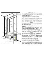
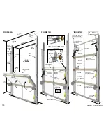
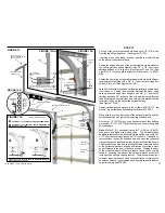
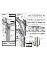
The top of the vertical tracks should be about 8-1/2“ (216) down
from the top of the closed door. (See Figures 13,13A)
If working alone, use a ladder or use a rope tied to a rafter to hold
up the back of the horizontal track.
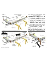
Fasten the curved front end of the left and right horizontal tracks to
the splice plates or splice brackets with 1/4" X 1/2" short neck
carriage bolts and 1/4" lock nuts. (See Figures 13, and 13A) See
Figure 13AA for splice plate extension for doors over 12’ (3660)
high.
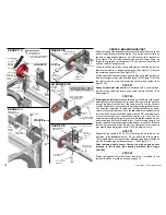
Fasten the front of the horizontal track angle to the top of the flag or
reverse bracket shields with a 3/8" X 1" short neck carriage bolt
and a 3/8" lock nut. (See Figures 14A,14B)
Level the horizontal tracks and set them parallel and square back
from the door. Fasten the horizontal tracks at the back, using
optional punched angle track hangers with 3/8" X 1" short neck
carriage bolts and 3/8" lock nuts. One of the bolts must go through
the back of each horizontal track as a safety bolt to prevent the top
roller from rolling out the back of the horizontal track.
(See Figures 13,13B)
Fasten optional punched angle to the ceiling with 5/16" X 2” lag
screws. Do not fasten a punched angle brace until STEP 27.
Make sure the curved front ends of the horizontal tracks and the
vertical tracks line up. Tighten the remaining bolts and nuts.
Doors over 14' (5270) high or any horizontal track that deflects
more than 1/2" (13) in 10' (3050) should also be center hung with
punched angle.
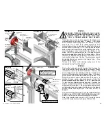
Note
: Martin 2" (51) horizontal tracks, for 7' (2130) to 14' (4270)
high doors, are made with slotted holes. The horizontal track
angles are fastened to the horizontal tracks slotted holes with 1/4"
X 1/2" short neck carriage bolts and 1/4" lock nuts. If needed, to
remove stress, loosen the bolts and nuts and move the horizontal
tracks or horizontal track angles, then re-tighten the bolts and nuts.
This procedure can also be used to slightly raise or lower the back
of the horizontal tracks to miss an obstruction or provide a more
perfect balance to the door in the open position. Raising the back
of the horizontal tracks will help to reduce the open door spring
tension. Lowering the back of the horizontal tracks will help to
increase the open door spring tension. The above procedure of
raising or lowering the back of the horizontal tracks, to improve the
open door balance, is sometimes used by professional installers,
only after completing STEP 26.
FIGURE 13AA
¼“ LOCK
NUTS
¼“ X ½” SHORT
NECK CARRIAGE
BOLTS
FLAG
SPLICE PLATE EXTENSION FOR ALL DOORS
OVER 12’ (3660) HIGH AND HI-LIFT DOORS
WITH T-LOCK HANDLE
OPTIONAL 3“ (76) VERTICAL TRACK EXTENSION KIT
OPTIONAL 6“ (152) VERTICAL TRACK EXTENSION KIT
-Can be cut to 3” (76)
EXCEPT MO, SP, OR SL DOORS.
EXTENSIONS OK TO USE WITH REGULAR FURNISHED HARDWARE
COPYRIGHT © 2004 MARTIN DOOR
¼“ X ½” SHORT
NECK CARRIAGE
BOLTS
ABOUT
8 ½“ (216)
SPLICE PLATE OR
SPLICE BRACKET


