***
STEP 8
CONTINUED***
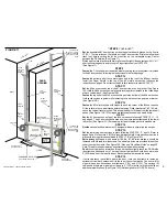
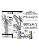
Set
the assembled #1 door section on the strips of cardboard, placed on the floor in
STEP 1. The two rollers on the left side of the #1 door section fit into the left vertical
track first, before setting the #1 door section on the cardboard strips. Center
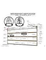
between the RA Shields. (See Figure 11)
Fit
the right vertical track over the two rollers on the right side and fasten with ¼“ x ½”
short neck carriage bolts and lock nuts. Finger tighten only until STEP 15.
(See Figure 11)
STEP 9
Fasten
the T-Lock handle of the optional safety spring latch lock system if provided
to the #2 door section, following the instructions in the lock package.
STEP 10
Fasten
the bottom half of the center hinges only to the top of the #2 door section.
Install the Finger Shield to the top of the #2
door section following the
instructions on page 5. Do not fasten the #2 roller brackets--fasten in STEP 12.
STEP 11
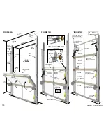
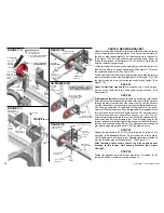
Set
the #2 door section on top of the #1 door section, at an angle first. (See Figure
12A) Hold the #2 door section in place with locking pliers clamped to the rolled edge
of each vertical track. (See Figures 12B)
Fasten
the top half of the #1 door section hinges to the bottom of the #2 door section.
Hold sections close together while fastening to keep the section gap to a minimum.
(See Figure 12B)
STEP 12
Fasten
the #2 roller brackets with hinges to each top corner of the #2 door section.
Fit the rollers in the vertical tracks before fastening. Roller brackets #1, #2, #3, etc.,
cause the vertical track to incline. This allows the door to lift away from the jambs as it
opens. (See Figure 12B,12D)
STEP 13
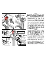
Set
the #3 door section on top of the #2 door section following STEPS 10, 11, 12,
and page 6. The #3 door section has the home owners packet fastened to the lower
left corner. (See Figure 12C) Screws are provided to fasten packet to wood doors.
STEP 14
Decide
optional window placement. A designer window is normally a top section.
STEP 15
Set
the remaining door sections in place following STEPS 10, 11, and 12. Refer to
pages 2 and 5 for doors to 9’ (2750) high with finger shield. Hold each door section in
place with locking pliers as explained in STEP 11. (See Figure 12C)
Push
the vertical tracks forward until the door sections lightly touch the RA Shields
then tighten all bolts and nuts. The top of the vertical tracks should be no more than
9 (229) down from the top of the door. Each side should measure the same.
STEP 16
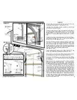
If extra clearance is available above the door, it may be desirable to fasten an
optional vertical track extension kit to the top of the vertical tracks. The door will lift
higher when open. Extensions available are 3”(76) and 6”(152). The springs, lift
cables and drums are made to provide up to 6” (152) of extra vertical track without
additional modifications. (See Figure 13C) (Not designed for MO, SP, SL doors.)
metal
Hinges are fastened face down on wood doors.
Extra heavy
doors and wood doors all #5, #6, #7, #8 roller brackets should be
fastened with 4 thread forming screws. The extra two holes are provided in the stiles,
under the steel door skin. (See Figure 12E) Also see “Wood Door Notes” on page 22.
Note: Thread forming screws can penetrate steel skin without drilling.
”
#1 DOOR
SECTION
LEFT
VERTICAL
TRACK
LEFT
JAMB
RIGHT
VERTICAL
TRACK
CE
ILIN
G
FLAG
SPLICE
PLATE OR
SPLICE
BRACKET
LEFT
RA OR RB
SHIELD
RIGHT
RA OR RB
SHIELD
A
R
HE
DE
WALL
CARDBOARD STRIPS
SEE FIGURE 1 AND STEP 1
FLOOR
ROLLER AND
ROLLER SHIELD
FINGER SHIELD
(FOR STEEL DOORS)
FINGER
SHIELD CLIP
(FOR STEEL
DOORS)
LIFT CABLE
LIFT
CABLE
LOCK-ON BOTTOM
ROLLER BRACKET
LOW
PROFILE
HINGE
FASTEN WITH
TWO ¼“ X ½” SHORT
NECK CARRIAGE
BOLTS AND LOCK
NUTS
FASTEN WITH
¼“ X ½” SHORT
NECK CARRIAGE
BOLT AND LOCK
NUT
9
FIGURE 11
ROLLER AND
ROLLER SHIELD
DOOR
OPENING
COPYRIGHT © 2004 MARTIN DOOR
ALL HINGES
FASTEN FACE
DOWN ON
WOOD DOORS


