background image

6

Cyclo user manual

To   e n s u r e   a d e q u a t e   v e n t i l a t i o n ,   w e
recommend that the Cyclo be installed with a
minimum of 25 mm (1 inch) of free space on
each side. Screw the fixture into place using,
either:

• 2 x 10 mm hardware together with the 

supplied washers, separated by 1 metre (3.3 

feet), or

• 4 x 8 mm hardware, in a matrix 1 metre by 

6.5 cm square

Connect the AC power and dimmer control wiring (as described in the
following sections) before replacing the wiring-housing cover, the tubes, and
the clear plastic cover.


A C   P O W E R

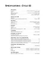
Maximum power usage data for the three Cyclo models in supplied in
“Specifications - Cyclo 02” on page 11.

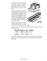
You can power Cyclo fixtures by wiring them in series. The internal wiring of
the fixtures carries AC power through the fixture. Holes are supplied at both
ends for input and output cables.

Warning:

In the Cyclo series fixtures incorporate a single electronic 
ballast per tube. Each of these “leaks” around 0,2 til 1 mA of 
power. Because of this we recommend connecting a maximum 
of 30 electronic ballasts (or tubes) per phase on a 30mA HPFI 
circuit breaker.

A normal 30 mA HPFI circuit breaker normally trips because of a 
current fault or leakage of approximately 20mA. It is important 
that the installation is carried out correctly in order to avoid 
unintentional tripping of the circuit breaker. 

Many installations use common neutral leads in branch circuit 
distribution boxes. It is important that the neutral lead in the 
cable is connected to the same HPFI circuit breaker, that it is 
not connected to the neutral leads from other HPFI circuit 
breakers. The neutral lead must be only associated with that 
specific circuit breaker. Additionally it is important that the 
fixtures are connected correctly to the ground (earth) to ensure 
that the power leakage is able to run off.

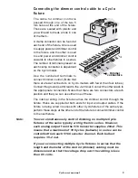
Ø10

Ø8

Ø8

Summary of Contents for CYCLO 02

Page 1: ...m a r ti na r c h i t e c t u r a l Cyclo user manual...

Page 2: ...o 03 Cyclo 02 Cyclo 02 Cyclo 04 Cyclo 04 2002 Martin Professional A S Denmark All rights reserved No part of this manual may be reproduced in any form or by any means with out permission in writing fr...

Page 3: ...A single 516 Controller can control 4 8 Cyclo groups individually each group consisting of one to ten of the same Cyclo model wired in series the number of groups depends on the model of Cyclo that is...

Page 4: ...tion from electric shock Disconnect the fixtures from AC power before removing or installing a lamp fuses or any part and when not in use Always ground earth the fixtures electrically Use only a sourc...

Page 5: ...ixture 1 Remove the fixture s clear plastic cover using a 2 5 mm Allen wrench 2 Carefully remove each of the tubes by rotating them at the ends until you are able to pull one end out and then remove t...

Page 6: ...cables Warning In the Cyclo series fixtures incorporate a single electronic ballast per tube Each of these leaks around 0 2 til 1 mA of power Because of this we recommend connecting a maximum of 30 e...

Page 7: ...in a series The number of terminals present on each clamp connector is dependent on the Cyclo model Use the three terminals not shaded in grey to connect AC power L live or positive N neutral and grou...

Page 8: ...ures 4 groups of 10 Cyclo 04s 40 fixtures or a combination of groups of up to 10 of each model Each output on the 516 II DMX to 0 10 V Converter is connected to both a 5 pin DIN socket and the 25 pin...

Page 9: ...te connectors Notes that there are two connectors at each position and that you can use either one of these The internal wiring in the fixture carries the dimmer control through the fixture Holes are...

Page 10: ...dentifying tube positions Tube positions are identified in the Cyclo 03 and Cyclo 04 as follows CL EANING We recommend that you clean the dust cover with a damp cloth Marking in fixture Marking on tub...

Page 11: ...4 watts THERMAL Maximum ambient temperature Ta 40 C 104 F DY NA MIC E FFEC TS Color temperature control 2700K up to 6000K Independent dimming of each tube via 516 Converter CONTROL VIA 516 CONV ERTER...

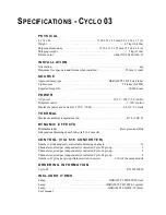
Page 12: ...power and current 230 V 50 Hz 0 42 A 96 watts THERMAL Maximum ambient temperature Ta 40 C 104 F DYNAMIC EFFECTS Dimmable tubes Red green and blue Independent dimming of each tube via 516 Converter C O...

Page 13: ...ACCESSORIES Martin 516 II DMX to 0 10V Converter P N 90758225...

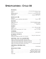
Page 14: ...z 0 56 A 128 watts THERMAL Maximum ambient temperature Ta 40 C 104 F DY NA MIC E FFEC TS Dimmable tubes Red green blue and white Independent dimming of each tube via 516 Converter CONTROL VIA 516 CONV...

Page 15: ...A CC E S S O R I E S Martin 516 II DMX to 0 10V Converter P N 90758225...

Page 16: ...www martin architectural com Olof Palmes All 18 8200 Aarhus N Denmark Tel 45 8740 0000 Fax 45 8740 0010...

Reviews: