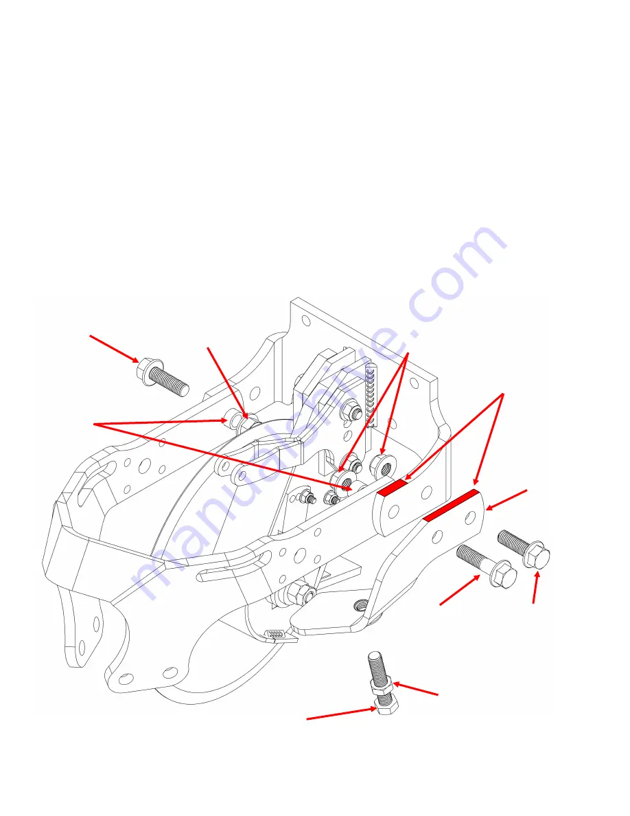
STEP 4 : ATTACH 1360 FRAME ASSEMBLY TO THE MOUNT
IMPORTANT:
Stop arm installation, as shown in the picture, is for the right UMO configuration . For a left
UMO configuration, install the right stop arm (STARM1360
-
5
-
8R) on the opposite side.
1.
Place the bushings (BU7858) inside the frame
’
s arms pin point holes.
2.
Align the holes in the mount and the frame assembly. Insert the
5/8”
x 2
1/2”
and the
5/8”
x
2”
bolts
from the outside. Add the Stop Arm and other
5/8”
x
2”
bolt as it is shown in the picture. Place nuts on
the
5/8”
bolts from inside and tighten the three bolts to 112 ft
-
lbs. Check after first day of use.
3.
Check to ensure the frame is not binding on the mounting bracket and is free to float up and down.
4.
If you don
’
t purchase the Optional Cam Adjustment ( Page 8), install the
5/8”
X
3”
bolt on the Stop Arm
as factory threaded adjustment assembly and tighten the
5/8”
Thin Nut to lock it after the adjustment.
6
5/8”
X
3”
BOLT (B5M58NC3)
BUSHINGS
(BU7858)
5/8”
FLANGE
LOCKNUTS
(N58FLN)
5/8”
X
2”
FLANGE BOLTS
(B5F58NC2)
5/8”
X 2
1/2”
FLANGE BOLTS
(B5F58NC212)
5/8”
FLANGE LOCKNUT
( N58FLN)
STOP ARM
(STARM1360
-
5
-
8L)
5/8”
Thin Nut ( N58CNLT)
5/8”
X
2”
FLANGE BOLTS
(B5F58NC2)
IMPORTANT
FLUSH THESE SURFACES BEFORE
TIGHTENING THE BOLTS
Summary of Contents for UMO-WA1360
Page 18: ...EXPLODED VIEW FOR WA1360 17 ...
Page 19: ...PARTS LIST FOR WA1360 18 ...


