background image

8

GB

14.95

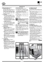
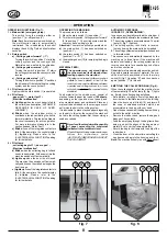
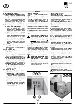
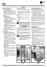
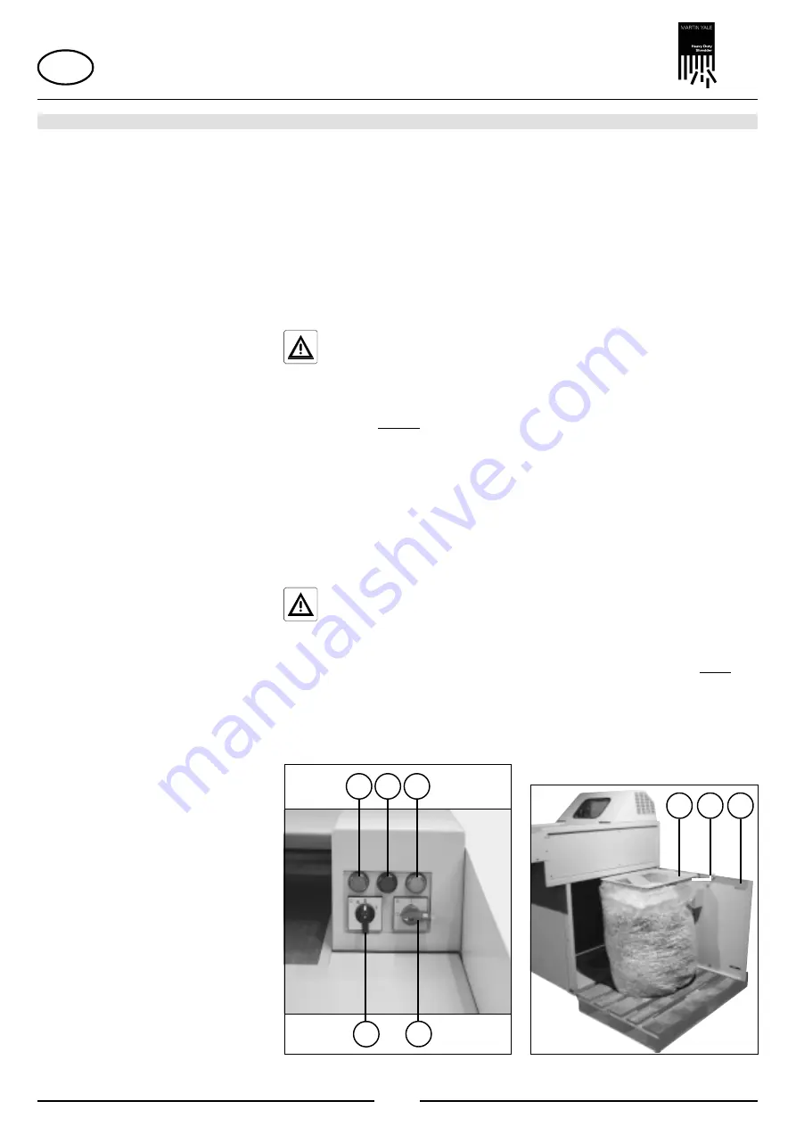
OPERATING FUNCTIONS (Fig. 7):
1 = Main switch (emergency-stop)

This switch turns the machine either on
(position „1“) or off (position „0“).

Note: 

Each time the machine is switched on,

the  multifunction  relay  is  automatically
reinitialised. This is indicated by the control
displays (4 and 5) (fig. 7) which blink for a few
seconds.

2 = Rotary switch

a) „Cutting system forward“ („1“)

Turning this switch to position „1“ starts the
cutting system and the conveyor belt.
Material can now be fed to the shredder.

b) „Cutting system reverse“ („R“)

Turning this switch to position „R“ starts
the cutting system and the conveyor belt in
reverse.

c) „Cutting system stop“ („0“)

Turning this switch to position „0“ switches
the shredder off, thereby halting the cutting
system and the conveyor belt.

3 = Pilot lamp „ready“

Lights when the main switch (1) is operated.

4 = Pilot lamp

„paper jam“ / „motor fault“ /
„Electrical malfunction“
a) Lights up
 when too much paper is fed to

the cutters (see description „AUTOMATIC
RESPONSE IN CASE OF OVER-
LOADING“).

b) Blinks when the shredder motor is

overloaded, thereby activating the built-in
thermal protection. This leads to a break in
the circuit necessary for active operation.
For more information please turn to the
section headed „Motor Fault“.

c) Blinks if one of the integrated contactors

fails. At the same time, the control display
(5)  lights up. Please refer to the
„ELECTRICAL MALFUNCTION“ heading
for further details.

5 = Pilot lamp

„collecting bag full“ / „door open“ /
„Electrical malfunction“
a) Blinks
 when the collecting bag is full and

needs to be emptied. At the same time the
machine switches off automatically.

b) Lights up when the door is not closed.

The machine then switches off automati-
cally and it cannot be started as long as the
door is open.

c) Lights up if one of the integrated contactors

fails. At the same time, the control display
(4)  blinks. Please refer to the
„ELECTRICAL MALFUNCTION“ heading
for further details.

OPERATION

OPERATING THE MACHINE:
The procedure is as follows:
1. Move the main switch (1) to position „1“.
2. Turn the rotary switch „Cutting system forward“

(2) to position „1“. The cutting system and the
conveyor belt now begin to run.

Attention: The machine will only operate when
a) the main switch (1) has been switched on

(position „1“),

b) the rotary switch (2) has been switched on

(position „1“ or ”R“),

c)

the discharge door (10) for emptying the bag is
closed.

MATERIAL FEED:

The operator may not stand higher
than the machine itself stands, when
feeding paper to the machine!

Standing on an raised platform (such as
pallets or boxes placed in front of the
machine) reduces the distance between
operator and cutting system to a level
which does not meet the required safety
standard.

Feed material for the shredder can consist of
stacks of smooth paper (up to about 190 sheets,
depending on the type and size of paper); and
also crumpled paper and cardboard. Place any
material to be shredded on the moving conveyor
belt which feeds it to the cutting system.
It is advisable to place stacked paper diagonally
on the belt. In this way, the corner of the stack will
be fed to the cutting system first, thus avoiding a
sudden overload.

Never feed the shredder with a quantity
of paper exceeding the maximum
indicated in the technical data!

Should the machine become overloaded,
follow the instructions under
„AUTOMATIC RESPONSE IN CASE OF
OVER-LOADING“.

AUTOMATIC RESPONSE
IN CASE OF „OVERLOADING“:
In case you accidentally overload the shredder, it
will automatically alleviate the problem as follows:
1. The cutting system becomes jammed. The pilot

lamp (4) (fig. 7) lights up.

2. The cutting system runs briefly in reverse,

thereby freeing the material to be shredded.

3. The cutting system automatically switches back

to forward mode.

This sequence is automatically repeated by the
machine  up  to  three  times.  If  the  machine  still
detects “overloading”, the cutting system runs in
reverse once more for a specified period of time
and is then shut down.
Redistribute returned material and continue shred-
ding with a smaller amount of material. The ma-
chine  must  first  be  switched  off  with  the  rotary
switch (2) (fig. 7) (position “0”), and then back on
again (position “1”) to this end.

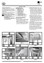
EMPTYING THE COLLECTING BAG (Fig. 8):
When the collecting bag is full, the machine turns
off automatically. The pilot lamp (5) (fig. 7) lights
up. Empty the collecting bag as follows:

- Set a pallet or a trolley in front of the discharge

door in order to facilitate removal of the full bag.

-

Open the door only a little bit (10) and level off
the  cone  of  shredded  material,  which  has
accumulated in the bag, with your hand.

- Open the door and swivel the bag frame with bag

out onto the pallet or trolley.

- Remove the rubber band, remove the bag and

dispose of its contents.

- Feed the empty bag through the bag frame from

below,  and  put  the  edges  of  the  bag  approxi-
mately 10 cm over the frame outwardly.

- Secure the bag to the frame with the help of the

rubber band.

- Close the door, at the same time swivelling the

bag frame and bag into the housing, and lock.

Note: The machine will only run with closed door!

fig. 8

9 11 10

fig. 7

1

2

3

4

5

Summary of Contents for 14.95

Page 1: ...la puesta en servicio Antes de pôr a máquina em funcionamento leia as instruções de operação Prima della messa in funzione leggere attentamente le istruzioni D GB F E P Seite 2 5 page 6 9 page 10 13 página 14 17 página 18 21 pagina 22 25 I Seite page 26 27 página pagina 26 27 Bedienungsanleitung Operating instructions Instructions d opération Instrucciones de uso Instruções de Operação Istruzioni ...

Page 2: ...ehäuse Seitenwand links und rechts abschrauben 2 Die beiden Schutzbleche 8 mit Hilfe der 2 zuvor abgeschraubten Schrauben an der Ge häuse Seitenwand links und rechts und mit den separat mitgelieferten jeweils 2 Schrau ben Muttern und Federringen außen am Tisch 7 festschrauben Hinweis Bei Bedarf kann durch das Anbringen zweier Schutzwinkel 15 Abb 5 anstelle der beiden Schutzbleche 8 Abb 4 eine Verb...

Page 3: ...richtung des Shredders überprüfen und ggf durch Phasentausch am Netzstecker richtigstellen Die Arbeit des Phasentausches am Netzstecker darf nur von einem Fachmann ausgeführt werden Wenn alles fachgerecht aufgestellt und ange schlossen ist kann die Inbetriebnahme erfolgen Das Gerät darf nicht von mehreren Personen gleichzeitig bedient werden Die Auslegung der Sicherheitselemente beruhen auf einer ...

Page 4: ...hen Sicherheits abstände zum Schneidwerk hin nicht zu lässig Glattes Papier wird stapelweise bis zu ca 190 Blatt je nach Ausführung und Papiersorte ge nauso wie Knüll Papier und Kartonagen auf das laufende Transportband gelegt und so dem Schneidwerk zugeführt Um eine schlagartige Belastung des Schneid werkes zu vermeiden ist es jedoch gut wenn Sie den Stapel aus glattem Papier schräg das heißt mit...

Page 5: ...inkenisteinerdereingebautenSchaltschütze nicht mehr funktionsfähig und die Maschine darf nicht weiter betrieben werden Schalten Sie die Maschine am Hauptschalter 1 Abb 7 aus ziehen den Netzstecker und be nachrichtigen Ihren Fachhändler Im Falle einer Reparatur ist vor dem Öffnen der Anlage der Netzstecker zu ziehen sowie der Hauptschalter aus zuschalten und mit einem Vorhänge schloß zu sichern SON...

Page 6: ...y piece to this end and the machine must be grasped lifted and set back down again with the pallet jack after each dismantling operation MOUNTING THE TABLE 7 fig 1 2 3 1 Remove the 3 screws from the housing front panel 6 as well as the 3 screws from the front of the conveyor belt retainer 13 2 Set the table 7 onto the conveyor belt retainer 13 push it all the way back to the housing 6 and secure i...

Page 7: ... CONNECTION a The maximum value for loop impedance at the mains connection point is 0 5 Ohms b Theconductorcross sectionofthepowersupply line should be of a magnitude so as to cause a 15 voltage drop in the case of a machine blockage inhibit current 3 x nominal current IMPORTANT SAFETY PRECAUTIONS Keepallloosearticlesofclothing ties jewelery long hair or other looseobjectsawayfromopening injury ma...

Page 8: ... when feeding paper to the machine Standing on an raised platform such as pallets or boxes placed in front of the machine reduces the distance between operator and cutting system to a level which does not meet the required safety standard Feed material for the shredder can consist of stacks of smooth paper up to about 190 sheets depending on the type and size of paper and also crumpled paper and c...

Page 9: ...ting system Note This involves no danger because all electri cal circuits are interrupted when the service flap is opened and the machine cannot be started GEAR BOX MAINTAINANCE Both synchron gears as well as the chain wheels and drive chains must be greased monthly The machine must be turned off at the main switch 1 fig 7 and unplugged before the machine is opened Proceed as follows 1 Remove the ...

Page 10: ...Remarque Il faut pour ce faire dévisser la palettepièceparpièce puisreprendreàchaque fois la machine avec le chariot élévateur la soulever et la redéposer MONTAGE DE LA TABLE 7 figures 1 2 3 1 Dévisser les 3 vis qui se trouvent à chaque fois sur la face avant du boîtier 6 et du côté frontal du support pour bande de transport 13 2 Poser la table 7 sur le support pour bande de transport 13 la faire ...

Page 11: ...ise en oeuvre partout où l on à besoin d une destruction à grande capacité de documents écrits Le destructeur détruit ausi facilement les cartonnagesetpapiersfroissésquelesfeuillesde papier lisses RECOMMANDATIONS IMPORTANTES DE SÉCURITÉ N approchez jamais du bloc de coupe les vêtements amples colliers cheveux longs cravates etc Il pourrait en résulter de sérieuses blessures N introduisez jamais le...

Page 12: ... machine Une surface surélevée par ex à l aide de palettes caisses etc devant la machine n est pas autorisée en vue des mesures de sécurité de distance au bloc de coupe On peut charger des tas de papier non froissés jusqu à une quantité d env 190 feuilles selon le bloc de coupe et le type du papier aussi bien que du papier froissé et des cartonnages sur la bande de transport qui se charge de l int...

Page 13: ... Performances de coupe 6x50 mm 120 130 feuilles 70 g m2 5 8 mm 130 140 feuilles 70 g m2 11 8 mm 180 190 feuilles 70 g m2 Largeur de travail 428 mm Puissance absorbée 7 kW Puissance débitée 4 kW Tensions de raccordement 400V 50Hz 230V 50Hz 415V 50Hz 220V 60Hz 200V 50Hz 200V 60Hz Fusible fusibles gl de classe 1 400V 415V 50Hz 25 A 220V 230V 50Hz 32 A 200V 50Hz 35 A Longueur 1680 mm Largeur 1210 mm H...

Page 14: ...tras otra todas las piezas de la paleta tenién dose que agarrar levantar y depositar cada vez de nuevo la máquina con ayuda de la carretilla elevadora MONTAJE DE LA MESA 7 figuras 1 2 3 1 Desenroscar en cada caso 3 tornillos en la pared delantera de la carcasa 6 y en la parte frontal del soporte de la cinta transportadora 13 Fig 3 Fig 2 7 14 6 Fig 1 7 13 6 Fig 4 7 8 6 Fig 6 7 14 12 12 Fig 5 7 15 2...

Page 15: ...ido de giro de la destructora de documentos y en caso necesario corregirlo cambiando las fases en el enchufe de red Los trabajos para el cambio de fases en el enchufe de la red sólo deben ser realizados por un técnico capacitado Una vez realizada una instalación y conexión correctas se puede proceder a la puesta en servicio 14 95 INDICACIONES DE SEGURIDAD IMPORTANTES El aparato no debe ser operado...

Page 16: ... puerta de extracción Abrir ligeramente la puerta 10 y aplanar en el saco o bolsa recogedora el cono formado por el material descargado Abrir la puerta y girar hacia fuera el marco de fijación con el saco o bolsa recogedora hasta que quede sobre la ayuda de transporte Retirar el cordón de goma desprender el saco o bolsa lleno y eliminar ecológicamente su contenido Pasarelsacovacíohaciaarribapordeb...

Page 17: ...e engrase 3 Montar la cubierta lateral izquierda y la caperuza y enchufar el conector de la red La máquina puede ser ahora puesta en marcha de nuevo No está permitido realizar ninguna modi ficación en la construcción de la máquina En caso de una no observación se pierde el permiso de explotación de la máquina SUGERENCIA PARA UN AHORRO DE ENERGIA Observar que la máquina se encuentre desconectada du...

Page 18: ...tarraxada peça por peça para isto e a máquina tem que serpegada levantadaedepositadanovamente com o carro de elevação MONTAGEM DAS CHAPAS DE PROTECÇÃO fig 4 1 Desaparafusar os 2 parafusos na parede late ral do cárter à esquerda e à direita 14 95 Fig 3 Fig 2 7 14 6 Fig 1 7 13 6 Fig 4 7 8 6 Fig 6 7 14 12 12 Fig 5 7 15 2 Atarraxarbemasduaschapasdeprotecção 8 com a ajuda dos 2 parafusos desaparafusado...

Page 19: ...irecção de marcha da trituradora ecorrigí laeventualmenteaosubstituirasfases na ficha de rede O trabalho para substituir as fases na ficha de rede só deve ser reali zado por um técnico especializado A colocação em funcionamento pode ser iniciada quando tudo é devidamente instalado e ligado 14 95 INSTRUÇÕES DE SEGURANÇA IMPORTANTES O aparelho não deve ser manejado por várias pessoas ao mesmo tempo ...

Page 20: ...e transporte em frente da porta de tirada Abrir um pouco a porta 10 e aplanar o cone de dejecção no saco de recolha com a mão Abrir a porta e girar o quadro do saco com o saco de recolha para fora até à ajuda de transporte Retirar a corda de borracha retirar o saco cheio e eliminar o conteúdo Conduzir o saco vazio a partir de baixo através do quadro do saco e virar o bordo do saco aprox 10 cm para...

Page 21: ...Controlar os três fusíveis de fases na tomada de corrente de rede e substituí los even tualmente Quando nehum dos pontos de controlo mencionados se confirma ou quando podem ser vistas outras funções falsas da máquina a máquina não deve ser accionada Contacte então por favor o seu revendedor especializado DADOS TÉCNICOS MANUTENÇÃO Proceder da maneira seguinte 1 Desmontar a cobertura lateral esquerd...

Page 22: ...per permettere questo il bancale deve essere smontato pezzo per pezzo e la macchina servendosi del carrello elevatore deveesserepresadinuovo sollevataedeposta 14 95 Fig 3 Fig 2 7 14 6 Fig 1 7 13 6 Fig 4 7 8 6 Fig 6 7 14 12 12 Fig 5 7 15 MONTAGGIO DEL PIANO 7 fig 1 2 3 1 Svitare le 3 viti della parete anteriore della cassa 6 e le 3 sul lato frontale del supporto del nastro di trasporto 13 2 Porre i...

Page 23: ...rimentodeldistruttore di documenti e se necessario correggere mediante inversione di fase sulla spina di rete L inversione di fase nella spina di rete deve essere eseguita da un elettricista qualificato Dopo aver correttamente installato e collegato la macchina si può eseguire la messa in funzione 14 95 IMPORTANTI ISTRUZIONI DI SICUREZZA L apparecchio non deve essere usato contemporaneamente da pi...

Page 24: ...rrello come aiuto per il trasporto Aprire leggermente la porta 10 e spianare con la mano il cono di entrata del materiale trinciato nel sacchetto di raccolta Aprire la porta e ruotare il telaio reggisacchetto sul mezzo di aiuto al trasporto Rimuovere la cordicella di gomma asportare il sacchetto pieno e smaltirne il contenuto Introdurre un sacchetto vuoto da sotto attraverso il telaioappositoerisv...

Page 25: ...ngrassare i componenti sopra descritti con un lubrificante normalmente reperibile in commercio applicato mediante un pennello o un ingrassatore 3 Montarecoperturalateraleecalottadicopertura e innestare il connettore dell alimentazione di rete La macchina può essere rimessa in funzione Non è consentito apportare alcuna modifica costruttiva In caso di non osservanza decade l omologazione della macch...

Page 26: ...0 Hauptschalter MAIN SWITCH INTERRUPTEUR GÉNÉRAL S2 Drehzahl Überwachung SPEDD CONTROL CONTRÔLE DE VITESSE S1 Schalter VOR ZURÜCK FORWARD and REVERSE ENTERRUPTEUR AVANT ET ARRIÉRE S3 Tür AUF DOOR OPEN PORTE OUVERTE 40 VA T1 L3 L1 L2 T3 T2 T1 X1 4 X1 8 X1 6 X1 10 X1 9 X1 5 X1 7 K2 K1 S3 S5 2 x 22k 9W 10 9 8 7 6 5 4 3 2 1 PE PE W V U PE N L3 L1 L2 1 1 I4 I5 I6 1 2 2 2 N 2 1 L I8 I7 I3 I1 I2 0 R 1 1 ...

Page 27: ...27 14 95 ...
Page 28: ...duct meets the following standards and guidelines Nous Vous Confirmons que l appareils cité ci dessus correspond aux exigences des directives 98 37 CEE des directives de basse tension 73 23 CEE ainsi qu à la directive CEM 89 336 CEE Classe B ci inclus toutes les modifications ainsi que tous les suppléments publiés jusqu à ce jour L appareil mentionné correspond aux normes citées ci après Confirmam...

Reviews: