background image

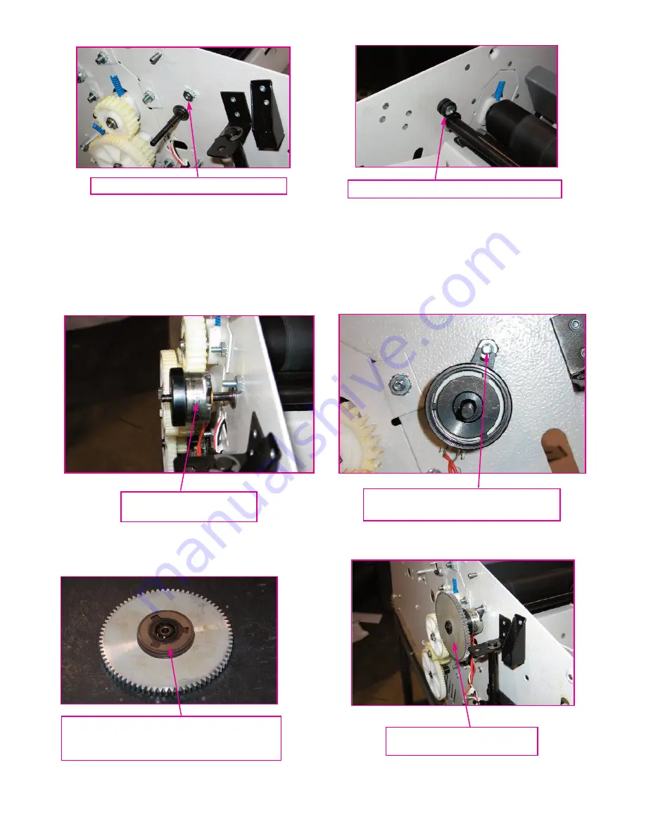
8)  Install electrical body of new clutch on feed shaft.  It may be necessary to turn clutch upon installa-

tion on the small end of the Feed Shaft to get their corresponding flats to align.  There is a certain

amount of ‘feel’ involved with installing the electrical portion of the clutch on the feed shaft end.  Do

not attempt to force the clutch onto the Feed Shaft.  When the flats of the (2) components are aligned,

the clutch will slip easily on the shaft.  During this installation, orient the clutch so that its anti-rotation

lugs align with the top cover grommet screw installed in step #7 above and push clutch onto shaft as

far as it will go.

9)  Install new clutch gear assembly on clutch making sure that the clutch friction disk is in assembly

(held to clutch gear assembly via permanent magnet).  Mesh the outer part of the gear with the exist-

ing folder gear & push on as far as it will go.

10)  Install .75” OD Fender Washer received with Retro-Kit on end of feed shaft.  Then install small E-

Ring to retain clutch in position.

Installing Electric Clutch

on Feed Shaft

Clutch Anti-Rotation Lugs Aligned

with Top Cover Grommet Screw

Clutch Gear Installed on

Magnetic Clutch

(4)

Make Sure that Friction Disk is at-

tached (magnetically) to Clutch Gear

with Smooth Side Towards Gear

Grommet Stop Screw & Kep Nut

Grommet Stop, Screw, and Standoff

Summary of Contents for 1812

Page 1: ...ded with the WRA1812510 Clutch Retrofit Kit 1 M S027951 Clutch Retro Kit Instructions this document 1 M S001540 8 32 X 7 8 Truss Head Screw 1 W O2051368 Black Oxide Feed Wheel Shaft for Disk Clutch 1 W O2051369 Clutch Feed Wheel 1 W A2051085 Disk Type Feed Clutch Assembly 1 M S008126 8 X 75 OD Fender Washer 1 M S010039 5133 18 E Ring 1 M S045339 1812 Processor 1 M S019032 1 4 X 3 8 X 17ID Standoff...

Page 2: ...e Feed Wheel in position 2 are located near the sideframes Slide feed shaft out of folder through sideframe with removed side cover Be careful not to lose plastic washers as they will be re used Remove old feed wheel and key and discard along with the Feed Shaft 4 Locate new Feed Shaft in Retro Kit Push shaft end opposite of small journal into rear sideframe in the opposite manner of the removed o...

Page 3: ...stment fully clockwise 6 Push both plastic spacers to their corresponding side frames Once both plastic spacers are in their proper locations the 4 E Rings removed in step 3 above may be re installed 7 Remove the top cover grommet stop screw on back side frame and replace with the longer one in cluded with retro kit Older machines may have a pressed stud in this location If this is the case drill ...

Page 4: ...ew installed in step 7 above and push clutch onto shaft as far as it will go 9 Install new clutch gear assembly on clutch making sure that the clutch friction disk is in assembly held to clutch gear assembly via permanent magnet Mesh the outer part of the gear with the exist ing folder gear push on as far as it will go 10 Install 75 OD Fender Washer received with Retro Kit on end of feed shaft The...

Page 5: ... with Retro Kit Carefully install in folder board opposite of old chip re moval Text on chip label should be oriented as shown in picture below Assure all chip pins are in serted in the mounting socket while pushing chip into position Basic static control precautions should be taken while this operation is being performed at the very least ground yourself before touching chip to eliminate static e...

Page 6: ...eset the paper retarder which is also called a sheet separator It is directly below the feed wheel Push the feed tray down and lock in the paper loading position lift the top cover 6 When Installing New Chip in Board Carefully Align Pins on Both Sides of Chip with Socket and Seat Chip Firmly Do Not Force Chip and Bend the Pins Bent Pins May Be Straightened but Will Require Even More Care in Instal...

Page 7: ... Wheel should turn freely If the retarder adjustment is incorrect insert the provided 9 64 hex wrench into the adjust ment hole Turn the wrench clockwise to loosen counterclockwise to tighten 7 Retarder pressure release button When you press this button and turn the Feed Wheel it should turn freely When you release this button you should feel the rubbing of the retarder against the Feed Wheel This...

Page 8: ...Y numbers associated with the other parts replaced 1812 with Disk Clutch Wiring Diagram 8 251 Wedcor Drive Wabash IN 46992 Phone 260 563 0641 Fax 260 563 4575 Website www martinyale com Email info martinyale com M S027951 6 16 15 REV 0 If you put one finger on each side of the retarder you should adjust the retarder pressure so the retarder just stops rock ing If the retarder is loose it will rock...

Reviews: