background image

5. Remove the safety plate by removing the two allen head screws that secure the safety plate to the frame.

a.

Loosen, but do not remove, the four 
allen head screws that hold the short 
(#6 in parts list) and long (#15 in parts 
list) spacers in the frames.  Remove the
screw and spacer located at top center 
between the front and back side frames 
(#16 in parts list).

b. Loosen the three remaining lower front 

frame allen head screws so that the 
screw head is approximately 1/2” away 
from the frame panel.  (See Figure #4)

c.

Slide the front frame away from the 
machine approximately 1/2”.

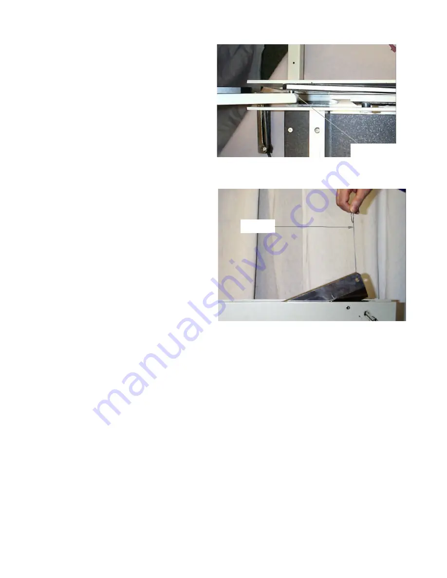
6. Separate the handle from the blade.  (See Figure 

#5)

a.

Grasp the handle and move the  handle 

and blade toward the loosened front 
plate. 
b. Move the handle back away from the 

blade to free the handle pin from the 
blade.  The handle pin is shown in
figure #5 and is attached to the handle.  
Lift the handle from the machine and 
set aside.

7. Using the blade tool (hook) remove the blade 

from the machine.  (See Figure #6)

a.

Place the hook into the blade pin hole in
the cutting blade.

b. Lift the front end of the blade and slide 

the blade out of the blade cam blocks 
(#24 in parts diagram).

c.

Secure the blade so that the cutting edge is not exposed.

d. Remove the blade cam roller from blade and save it for reinstalling the blade.

4.4.3

Blade Installation

NOTE: Whenever a different blade is installed, you must level the blade after reassembly is complete.

1. Lubricate the blade assembly roller and install it on the blade pin (the pin that is permanently attached to the blade)
2. Insert the blade into the frame so that the blade assembly roller is between the blade cam blocks (See Figure #24 in 

parts diagram for blade cam block location).

3. Insert the blade tool (hook) into the front blade pin hole and lower the blade into the frame so that the cutting edge 

rests on the surface of the cutting stick.

4. Reattach the handle to the cutting blade.
5. Push the front plate toward the machine.
6. Tighten the long and short spacer screws (See #15 and #6 in parts diagram for long and short spacer location).  

Install and tighten screw and spacer located at top center between the front and back frames (See #16 in parts dia--
gram).

7. Install the top cover on the frame.
8. Install the blade safety plate and level blade (see section 4.3.2).
9. Install the front (small ) wood deck.

(5)

Handle Pin

Step 7

Figure #5

Figure #6

Summary of Contents for 7000E

Page 1: ...ith recommended maintenance the unit will provide years of trouble free service Please review this publication in its entirety before attempting to operate your 7000E Thorough understanding of this information will help eliminate most operator associated errors and ensure years of trouble free performance WARNING The cutting blade of the 7000E is extremely sharp Never place hands or fingers under ...

Page 2: ...ack gauge is secured in position on the side rail with the locking knob 4 Note the measuring scale on top of the side rail The scale is calibrated in both inch and metric readings that provide accurate back gauge settings 3 0 OPERATION Do not attempt to operate the 7000E until you have read and thoroughly understand this manual The following procedure should be followed when loading cutting and un...

Page 3: ...esh side See 4 4 1 This condition may occur if the blade is not level with the cutting stick See 4 3 2 7 Return the blade handle to the fullest upward position Make sure the blade handle is securely locked in place by the safety latch 8 Raise the paper clamp with counter clockwise rotation of the clamp wheel 9 Remove all cut material from the 7000E 4 0 MAINTENANCE Please refer to the diagram and p...

Page 4: ...he handle down and turn the cut depth adjustment screw clockwise until it contacts the blade Turn the adjusting screw 1 8 turn counterclockwise and tighten the lock nut NOTE Blade should cut a maximum of 1 32 into the stick 4 4 Parts Replacement 4 4 1 Rotating or Replacing The Cutting Stick To rotate or replace the cutting stick follow this procedure 1 Raise the handle and make sure it is locked b...

Page 5: ...and slide the blade out of the blade cam blocks 24 in parts diagram c Secure the blade so that the cutting edge is not exposed d Remove the blade cam roller from blade and save it for reinstalling the blade 4 4 3 Blade Installation NOTE Whenever a different blade is installed you must level the blade after reassembly is complete 1 Lubricate the blade assembly roller and install it on the blade pin...

Page 6: ...er 14 M O007034 1 Cutting Stick 15 M O007010 1 Long Spacer 16 M O007039 1 Upper Frame Spacer 17 W A007002 1 Main Frame Assy Item Part Qty Description 17A M S030003 4 Frame Feet 18 W A007005 1 Clamp Mount Plate 19 WRA007006 1 Clamp Assy 19A M O007030 1 Clamp Rubber Strip 20 W A007015 1 Top Cover 20A M S001129 1 Top Cover Screw 21 M O007013 1 Clamp Adjust Screw 21A M S010033 1 Retaining Ring 21B M S...

Page 7: ... 7 6 0 7000E Parts Diagram ...

Page 8: ...in Section 4 4 2 NOTE As an average the cutting blade should be sharpened or replaced after eight cutting hours of 24 bond paper 90g m2 Cutting heavier or more abrasive material may necessitate more frequent sharpening or replacement of the blade 7 3 Cut Paper Is Out Of Square Make sure the paper stack is correctly aligned to the side rail and back gauge Also make sure the paper stack is correct l...

Reviews: