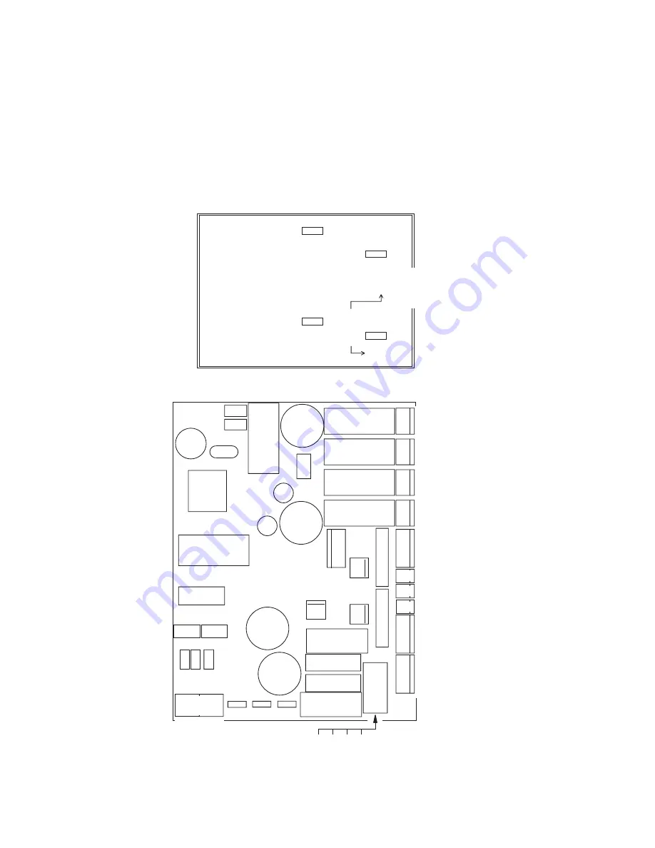
Printed circuit board layout
63
Printed circuit
board layout
PL5
PL13
PL11
PL12
PL17
PL16
PL19
PL20
PL21
PL22
Bat.
Power
M
M
M
M
PL1
PL3
PL8
PL9
PL2
PL10
PL14
PL15
Terminal
DMX
FAN
12V
Magenta
Cyan
Yellow
Dimmer
Fuse T2AT
Fuse T2AT
Bat.:
3V
Lithium
Bat.:
3V
Lithium
PL24
Ext.
Init
Lock
Boot
Disable
Enable
W
rite
Flash
T
X+R
X
TX
+
RX
RX
only
RX
only
sensor Heat
Det
ails
Protective
Gnd.
Protective
Gnd.
Hot
Cold
Protective
Gnd.
Protective
Gnd.
LED's
24V
AC
24V
AC
12V
AC
12V
AC
1
P/N
33120026-B
P/N
33120026-B
FAN
FA
N
Ef
fect
module
Ef
fect
module
FA
N
Power
module
Power
module
PL
11
PL
17
PL
10
PL
24
PL
1
PL
2
1
1
1
12V
24V
Light
sensor
Light
sensor
PL
8
Default
Summary of Contents for Exterior 200
Page 1: ...Exterior 200 user manual mar tinar chi tect ura l ...
Page 5: ...5 SECTION 1 GETTING STARTED ...
Page 27: ...General operation 27 SECTION 2 STAND ALONE OPERATION ...
Page 48: ...48 Synchronous triggering during Stand Alone operation ...
Page 49: ...Synchronous triggering during Stand Alone operation 49 SECTION 3 DMX CONTROL ...
Page 53: ...DMX Controller operation 53 SECTION 4 OPTICS ...
Page 57: ...Lens options 57 SECTION 5 SERVICE AND TROUBLESHOOTING ...
Page 65: ...SECTION 6 REFERENCE ...
Page 75: ......


