10
P3-100 user manual
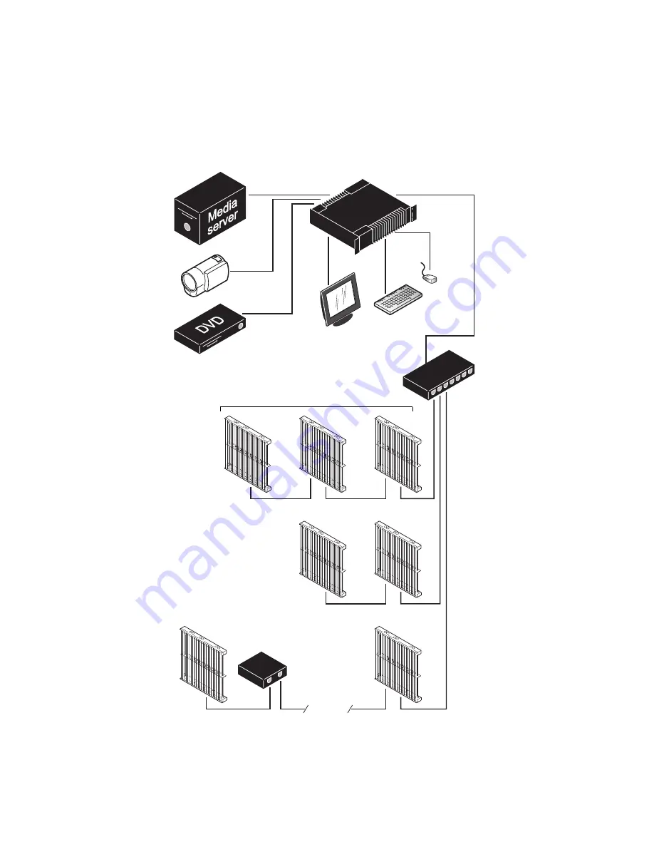
System layout
Figure 3 is given for reference only and shows how an entire system consisting of a P3-100 System
Controller and LC Plus panels should be laid out and connected. For full details of panel installation –
including important safety information – refer to the LC Plus user documentation supplied with panels and
available for download free of charge from www.martin.com
Figure 3: System layout
DVI
Analog
video
Analog
video
Monitor
Mouse
Keyboard
P3-100 Controller
P3 signal
1GB Ethernet
switch required
1GB Ethernet
switch required
100 m
Max. 50 panels per daisy-chain
if installation
exceeds 50 panels
if cable length
exceeds 100 m
cable


