Taking all necessary safety precautions connect the test leads to
the circuit being measured and read the measured % duty cycle
from the display.
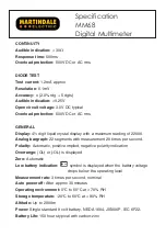
3.17 Continuity Testing
Connect the black test lead to the COM terminal and the red test
lead to the %HzV
Ω
terminal.
Set the rotary switch to
.
Taking all necessary safety precautions connect the test leads to
the circuit being tested.
The buzzer will sound if the resistance is <30
Ω
.
3.18 Diode Testing
If the diode to be tested is in circuit be sure the circuit power is
switched off.
Connect the black test lead to the COM terminal and the red test
lead to the %HzV
Ω
terminal.
Set the rotary switch to
.
Taking all necessary safety precautions connect the test leads to
the diode being tested.
If the diode is good a forward bias will give a display reading of
around 0.6 V (silicon diode) and a reverse bias will give a display
of OL. If the diode is shorted or open circuit the display will
indicate approx 0V or OL respectively for both forward and reverse
bias.
10
Summary of Contents for MM68
Page 1: ...MM68 MULTIMETER Instruction Manual ...
Page 23: ...USER NOTES ...


