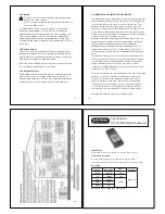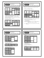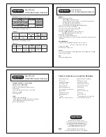
Auto or manual ranging
Auto power off
2.3 Accessories
The MM94 comes with the following accessories:
TL16 test leads
TT1P Type K thermocouple
9V PP3 battery (Installed)
Instructions
3. OPERATION
3.1 General
If the magnitude of a parameter to be measured is uncertain, but
known to be within the maximum safe limits of the electrical tester,
manually set the range to maximum. E.g. If measuring AC voltage
and the voltage magnitude is unknown, set the range to 750 V,
then if required select the correct range for a satisfactory reading.
If the insulation clamp meter displays
OL
or
-OL
then the
measurement limits of the range have been exceeded.
3.2 Low Battery Indication
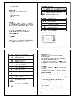
The battery capacity is shown by one of the following symbols on
the LCD:
If the symbol is displayed, the battery needs replacing as
measurement accuracy can no longer be guaranteed (See section
4.1 Battery Replacement). This will be followed by a
bAtt
display
and the multimeter will power down after 5 seconds.
6
3.3 Description of Terminals
20A
Input terminal for AC & DC current measurements to 20A
μA mA
Input terminal for AC & DC current measurements to 400 mA
COM
Common terminal
nsHz%
V
:
Input terminal for AC and DC voltage, resistance,
conductance, continuity, diode test , frequency and duty cycle
K-TYPE
Input terminals for temperature probes
3.4 Description of Press Buttons
RANGE
Selects manual ranging
REL
Selects relative function
MIN/MAX
Selects min/max function
HOLD
Selects display hold function
PEAK ±
cal>2s
Selects peak hold measurement
Turns on/off the backlight
SHIFT
Selects secondary functions
HFR
Selects -3db point of high frequency rejection filter
6000
Sets display to 6000 counts
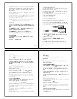
3.5. Description of LCD Symbols
7
HFR1
High frequency reject > 1 kHz selected
HFR 2
High frequency reject > 100 kHz selected
RANGE
Manual ranging is selected
MAX
Maximum indication is displayed
MIN
Minimum indication is displayed
HOLD
Display hold is activated
P+
Indicates peak + measurement
P-
Indicates peak - measurement
REL
Relative function selected
Indicates >30V at input terminals
AC
Indicates AC measurement
DC
Indicates DC measurement
AC
+
DC
Indicates AC + DC measurement
APO
Auto power off is activated
Indicates battery level
Diode testing function is selected
Continuity function is selected
mV, V,
μA, mA, A,
nF, μF, mF,
:
, k
:
, M
:
,
nS,
Hz, kHz, MHz,
%,
°C, °F
Units of measurement being displayed
8
3.6 Auto Power Off
If the multimeter is inactive for a period of 30 minutes it will
automatically power off.
If any button is pressed after the clamp meter has automatically
powered off, the clamp meter will turn back on.
To disable the auto power off function hold the
MIN/MAX
button at
the same time as turning the rotary switch from
OFF
to any position.
The
APO
symbol will no longer be displayed on the LCD.
3.7 Backlight
To switch on the backlight press the
button. Press again to turn
the backlight off.
The backlight will automatically power off after approx. 3 minutes.
3.8 Auto/Manual Ranging
To select manual ranging, press the
RANGE
button. The
RANGE
symbol will be displayed on the LCD.
To manually select a range when in manual mode press the
RANGE
button until the required range is selected.
To exit manual ranging, hold down the
RANGE
button for >2
seconds. The
RANGE
symbol will no longer be displayed.
3.9 Relative Function
The relative function is used to remove an offset or residual value
from a measurement.
To remove and store an offset to memory, press the
REL
button.
The LCD will display the
REL
symbol and the offset will be
removed from all consequent readings until the relative mode is
deactivated.
9


