
To view the measured value without the offset being removed from
the measurement and without losing the stored offset from memory,
press the
REL
button again. The LCD will display the
REL
symbol flashing.
Pressing the
REL
button once more will again remove the stored
offset from the measurement.
To exit the relative function press the
REL
button for >2 seconds.
The LCD will no longer display the
REL
symbol and the stored
offset will be deleted from memory.
Note: Changing range or measurement function will also exit the
relative function and any stored offset will be lost.
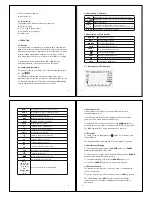
3.10 Min/Max
To activate the Min/Max function, press the
MIN/MAX
button. The
multimeter exits autorangeing and the LCD will display
RANGE
and
MAX
.
Press
MIN/MAX
as required to alternate between displaying the
maximum and minimum measured values.
Press
MIN/MAX
for >2 seconds to exit the Min/Max function.
Note: Pressing the
RANGE
button will exit the Min/Max function.
3.11 Display Hold
To hold a displayed value, press the
HOLD
button. The LCD will
display
HOLD
.
Press again to exit display hold.
10
3.12 High Frequency Rejection
If the AC voltage ranges are selected, there is a choice between
two high frequency rejection filters.
The multimeter defaults to
HFR 2
(100kHz - 3dB point). The LCD
will display the
HFR 2
symbol.
To select
HFR1
(1kHz - 3dB point), press the
HFR
button. The
LCD will display the
HFR1
symbol.
Press again to return to HFR2.
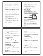
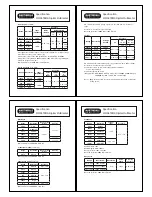
3.13 Use of the TL16 Test Leads
Before use, always check the continuity of the test leads.
Where access to test points may require extended probe tips, the
probe tip caps may be removed by gently pulling them forward until
they unclip from the probe body.
CAT III 1000V
CAT IV 600V
CAT II 1000V
ONLY
DO NOT USE ON
CAT III or CAT IV
installations
3.14 AC Voltage Measurements
Connect the black test lead to the
COM
terminal and the red test
lead to the
terminal.
Set the rotary switch to the
HFRm
V
or
HFR
V
position as
required.
Set the high frequency rejection as required (see section 3.12).
Taking all necessary safety precautions connect the test leads to
the circuit being measured and read the measured ac voltage from
the display.
11
3.15 DC Voltage Measurements
Connect the black test lead to the COM terminal and the red test
lead to the
terminal.
Set the rotary switch to the
or
position as required.
Taking all necessary safety precautions connect the test leads to
the circuit being measured and read the measured dc voltage from
the display.
3.16 AC+DC Voltage Measurements
Connect the black test lead to the COM terminal and the red test
lead to the
terminal.
Set the rotary switch to the
or
position as required.
Press the
SHIFT
button. The LCD will display the
symbol.
Taking all necessary safety precautions connect the test leads to
the circuit being measured and read the measured ac+dc voltage
from the display.
3.17 Current Measurements
Connect the black test lead to the
COM
terminal and the red test
lead to the
μA mA
or
20A
terminal as required.
Set the rotary switch to the
or
position as required.
The multimeter defaults to dc current measurement. The LCD will
display the
DC
symbol.
To measure ac current press the
SHIFT
button. The LCD will
display the
AC
symbol.
Press
SHIFT
again to measure ac+dc current. The LCD will display
12
the
symbol.
Pressing
SHIFT
once more will revert back to dc current
measurement.
Taking all necessary safety precautions connect the test leads to
the circuit being measured and read the measured dc, ac or ac+dc
current from the display.
3.18 Peak Hold Measurement
To record the peak+ or peak- value when making AC voltage or AC
current measurements press the
button for >2 seconds.
The LCD will display
CAL
followed by
P+
and the measured peak +
value.
To display the measured peak - value, press the
button. The
LCD will display
P-
.
To exit the peak measurement function, press the
button for >2
seconds.
3.19 Resistance Measurements
Connect the black test lead to the
COM
terminal and the red test lead
to the
terminal.
Set the rotary switch to the
position.
Taking all necessary safety precautions connect the test leads to the
circuit being measured and read the measured resistance from the
display.
3.20 Conductance Measurements
Connect the black test lead to the
COM
terminal and the red test lead
to the
terminal.
13


