

Set the rotary switch to the
position.
Press the
SHIFT
button three times. The LCD will display the
nS
symbol.
Taking all necessary safety precautions connect the test leads to the
circuit being measured and read the measured resistance from the
display.
Note: Display resolution is 6000 counts only, for the conductance
function.
3.21 Capacitance Measurements
Be sure the capacitor being tested is completely discharged
before connecting the test leads.
Connect the black test lead to the
COM
terminal and the red test
lead to the
μA mA
terminal.
Set the rotary switch to the
position.
Taking all necessary safety precautions and observing the correct
polarity for electrolytic capacitors, connect the test probes to the
capacitor to be measured.
Read the measured capacitance from the display.
Note: Display resolution is 6000 counts only, for the capacitance
function.
3.22 Frequency and Duty Cycle Measurements
Connect the black test lead to the
COM
terminal and the red test
lead to the
terminal.
Set the rotary switch to the
Hz %
position.
Taking all necessary safety precautions connect the test leads to the
14
circuit being measured and read the measured frequency from the
display.
To display the measured duty cycle press the
SHIFT
button. The
LCD will display the
%
symbol.
Press again to revert back to measured frequency.
3.23 Temperature Measurements
Set the rotary switch to the
°C °F
position.
The multimeter defaults to measurement in °C.
For measurement in °F press the
SHIFT
button.
Press again to revert back to °C.
Connect a Type K thermocouple probe, suitable for the type of
temperature measurement and temperature range being made, to
the
K-TYPE
sockets.
Taking all necessary safety precautions position the thermocouple
at the surface or in the medium to be measured and read the
measured temperature from the display.
3.24 Continuity Testing
Connect the black test lead to the
COM
terminal and the red test
lead to the
terminal.
Set the rotary switch to the
position.
Press the
SHIFT
button once. The LCD will display the
symbol.
Taking all necessary safety precautions connect the test leads to
the circuit being tested.
If the resistance is <40
:
, the buzzer will sound continuously. The
resistance value will be displayed if
d
600
:
.
15
3.25 Diode Testing
If the diode to be tested is in circuit, be sure the circuit power is
switched off.
Connect the black test lead to the
COM
terminal and the red test
lead to the
terminal.
Set the rotary switch to the
position.
Press the
SHIFT
button twice. The LCD will display the
symbol.
Taking all necessary safety precautions connect the test leads to
the diode being tested.
If the diode is good a forward bias will give a display reading of
around 0.6V (silicon diode) and a reverse bias will give a display of
OL
. If the diode is shorted or open circuit the display will indicate
approx. 0V or
OL
respectively for both forward and reverse bias.
4. MAINTENANCE
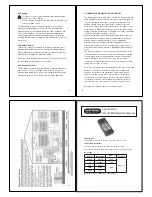
4.1 Battery Replacement
To avoid shock, injury or damage to the multimeter,
disconnect it from any external circuits or components and
remove the test leads before proceeding.
The battery compartment is inside the unit and can be accessed
by undoing the 4 screws securing the rear casing using a Phillips
head screwdriver, and removing the rear casing.
Fit a new 9V, PP3 alkaline battery (IEC 6LR61, NEDA 1604A)
observing correct polarity.
Replace the rear casing and screws.
16
4.2 Fuse Replacement
To avoid shock, injury or damage to the multimeter,
disconnect it from any external circuits or components
and remove the test leads and battery before proceeding.
Replace only with the fuses specified.
The fuses are inside the unit and can be accessed by undoing
the 4 screws securing the rear casing using a Phillips head
screwdriver, and removing the rear casing. Remove the protective
cover from fuse F1 if required.
Replace F1 only with the original type 0.5 A/1000V 6.3x32mm fast
blow ceramic fuse.
Replace F2 only with the original type 20 A/600V 10x38mm fast
blow ceramic fuse.
Replace the fuse protective cover over F1, then the rear casing
and screws.
4.3 Test Lead Replacement
If the test leads become damaged they should be replaced.
The replacement test leads must have the same (or
better) overvoltage category rating as the TL16 test leads
supplied.
4.4 Calibration
To maintain the integrity of measurements made using your
instrument, Martindale Electric recommends that it is returned
at least once a year to an approved Calibration Laboratory for
recalibration and certification.
Martindale Electric is pleased to offer you this service. Please
contact our Service Department for details.
Email: service@martindale-electric.co.uk
Tel: 01923 650660
17


