Maruson Technology Corporation
12
ULTIMA SERIES 1K-3KVA | 2012 Jan.
l
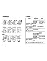
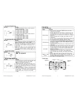
05: Bypass Mode Enable/Disable
Interface
Setting
ENA: Bypass mode enabled
DIS: Bypass mode disabled
l
06: Bypass Voltage Range Setting
Interface
Setting
Press the Down key or Up key to set the acceptable high
voltage point and acceptable low voltage point:
HLS: Bypass high voltage point
LLS: Bypass low voltage point
For 208/220/230/240 VAC models:
230-264: setting the high voltage point from 230Vac to
264Vac
170-220: setting the low voltage point from 170Vac to
220Vac
For 110/115/120/127 VAC models:
120-132: setting the high voltage point from 120Vac to
132Vac
85-115: setting the low voltage point from 85Vac to
115Vac
l
00: Exit Setting
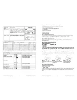
3-6. Operating Mode Description
Operating
Mode
Description
LCD Display
Online mode
When the input voltage is within
acceptable range, UPS will provide pure
and stable AC power to output. The UPS
will also charge the battery at online
mode.
ECO mode
Energy saving mode:
When the input voltage is within voltage
regulation range, UPS will bypass
voltage to output for energy saving.
Battery mode
When the input voltage is beyond the
acceptable range or power failure and
the alarm is sounding every 4 seconds;
UPS will backup power from battery.
Maruson Technology Corporation
7
ULTIMA SERIES 1K-3KVA | 2012 Jan.
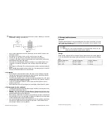
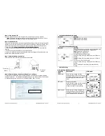
Step 5: Turn On the UPS
Press the ON/Mute button on the front panel for two seconds to power on the UPS.
Note: The battery charges fully during the first five hours of normal operation. Do not
expect full battery run capability during this initial charge period.
Step 6: Install Software
For optimal computer system protection, install UPS monitoring software to fully configure UPS
shutdown. You may insert provided CD into CD-ROM to install the monitoring software. If not,
please follow steps below to download and install monitoring software from the internet:
1. Go to the website http://www.power-software-download.com
2. Click the ViewPower software icon and then choose your required OS to download the
software.
3. Follow the on-screen instructions to install the software.
4. When your computer restarts, the monitoring software will appear as an orange plug icon
located in the system tray near the clock.
Step 7: External Battery Connection
Follow the below chart to make external battery connection.
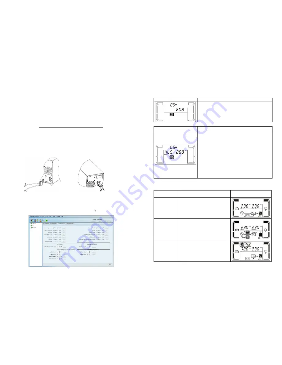
Step 8: External Battery Capacity Configuration in Software
To calculate accurate backup time of external batteries, it’s necessary to configure battery
numbers in software. The standard calculated capacity for one battery is 9Ah. If connecting
to 100Ah batteries, then it’s equal to 11 in parallel (100Ah / 9Ah 11 sets).
To external
battery
To external
battery


