background image


15 

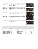
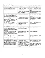
Buck mode when 

AC is normal.   

When the input voltage is higher than the voltage 

regulation range but lower than high loss point, the buck 
AVR will be activated. 


Boost mode when 

AC is normal.   

When the input voltage is lower than the voltage regulation 

range but higher than low loss point, the boost AVR will be 
activated. 


Battery mode 

When the input voltage is beyond the acceptable range or 

power failure, the UPS will backup power from battery and 
alarm is sounding every 10 seconds.   


Standby mode 

UPS is powered off and no output supply power, but still 

can charge batteries. 


Fault mode 

When a fault has occurred, the ERROR icon and the fault 
code will be displayed. 


3-7. Faults Reference Code 

Fault event 

Fault code    Icon  Fault event 

Fault code    Icon 

Bus start fail 

01 

Inverter output short 

14 

Bus over 

02 

Battery voltage too 

high 

27 

Bus under 

03 

Battery voltage too low  28 

Inverter soft start fail  11 

Over temperature 

41 

Inverter voltage high 

12 

Overload 

43 


Inverter voltage Low 

13 

Charger failure 

45 


Summary of Contents for Ultima LiFe RT 1.5K

Page 1: ...Maruson Technology Corporation 16050 Kaplan Ave City of Industry CA 91744 U S A Tel 1 714 870 6888 Fax 1 714 870 4888 Toll Free 1 888 MARUSON Website www MarusonUSA com E Mail Info MarusonUSA com All...

Page 2: ...principle 5 2 3 Install The UPS Only for RT Models 5 2 4 Setup The UPS 6 2 5 Battery Replacement 8 3 Operations 10 3 1 Button Operation 10 3 2 LCD Panel 10 3 3 Audible Alarm 11 3 4 LCD Display Wordin...

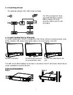
Page 3: ...laser printers to the UPS output sockets Place cables in such a way that no one can step on or trip over them The UPS can be operated by any individuals with no previous experience Connect the UPS sy...

Page 4: ...tage exists in the terminals of high capability capacitor such as BUS capacitors To avoid electrical shock turn off the unit and unplug it form the AC power source before servicing the battery Only pe...

Page 5: ...d if not installed and used in accordance with the instructions may cause harmful interference to radio communications However there is no guarantee that interference will not occur in a particular in...

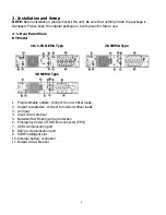
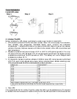
Page 6: ...RT Model 1K 1 5K NEMA Type 2K NEMA Type 3K NEMA Type 1 Programmable outlets connect to non critical loads 2 Output receptacles connect to mission critical loads 3 AC input 4 Input circuit breaker 5 N...

Page 7: ...install the UPS please follow below steps to re connect battery wires first Step 1 Step 2 Step 3 Remove front panel Connect the AC input and re connect battery wires Put the front panel back to the u...

Page 8: ...full load The highest working temperature requirement for UPS operation is 50 C The battery can not be charged when temperature is above 50 C 3 It s required to maintain maximum altitude of 1000m to k...

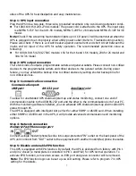
Page 9: ...critical devices by setting shorter backup time for non critical devices Step 3 Communication connection Communication port USBport RS 232 port Intelligent slot To allow for unattended UPS shutdown st...

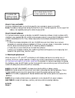
Page 10: ...r as an orange plug icon located in the system tray near the clock 2 5 Battery Replacement When the icons of and are flashing in LCD display and alarm is sounding every 2 seconds it s time to replace...

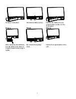
Page 11: ...ll out the battery box by removing two screws on the front panel Step 4 Step 5 Step 6 After replacing the batteries put the battery box back to original location and screw it tightly Re connect the ba...

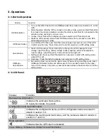
Page 12: ...t frequency battery voltage battery capacity ambient temperature output voltage output frequency load current and load percent Setting mode Press and hold this button for 3 seconds to enter UPS settin...

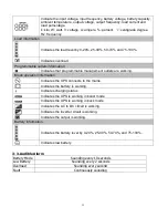
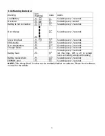
Page 13: ...outlets are working Mode operation information Indicates the UPS connects to the mains Indicates the battery is working Indicates charging status Indicates the UPS is working in boost mode Indicates t...

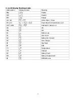
Page 14: ...able ESC Escape AO AC Active Open Close ST1 2 3 Input Waveform Sensitivity 1 2 3 AUT AON Automatic Always on OK OK ON ON BL Battery Low OL Over Load NC Battery No Connect OC Over Charge SF Site Fault...

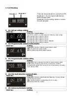
Page 15: ...125Vac 02 Programmable outlets enable disable Interface Setting Parameter 2 Enable or disable programmable outlets ENA Programmable outlets enable DIS Programmable outlets disable Default 03 Programma...

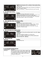
Page 16: ...ting Parameter 2 Set Input Waveform Sensitivity St1 Input voltage waveform detection is highly sensitive Default St2 Input voltage waveform detection is middle sensitive St3 Input voltage waveform det...

Page 17: ...PS will backup power from battery and alarm is sounding every 10 seconds Standby mode UPS is powered off and no output supply power but still can charge batteries Fault mode When a fault has occurred...

Page 18: ...every 2 seconds EPO enable Sounding every 2 seconds Over temperature Sounding every 2 seconds Charger failure Sounding every 2 seconds Battery fault Sounding every 2 seconds At this time UPS is off to...

Page 19: ...sounding every 2 seconds The external or internal battery is incorrectly connected Check if all batteries are connected well Fault code is shown as 27 and the icon is lighting on LCD display and alar...

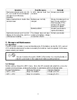
Page 20: ...d battery voltage is less than 10V PC Contact your dealer 5 Storage and Maintenance 5 1 Operation The UPS system contains no user serviceable parts If the battery service life 3 5 years at 25 C ambien...

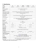
Page 21: ...AC Mode 96 7 Buck Boost Mode 93 for 120VAC models Battery Mode 75 load 88 90 90 5 BATTERY Battery Type LIFE 247500 LIFE 485000 LIFE 722500 Battery Number 1 1 2 2 3 Charging Voltage 28 VDC 1 52 5 VDC...

Reviews: