background image


Operation Manual 


Maruyama Boom Sprayer 


Be sure to read before use. 

BSA-500-1 
BSA-500-J 
BSA-500-JQ 

Summary of Contents for BSA-500-1

Page 1: ...Operation Manual Maruyama Boom Sprayer Be sure to read before use BSA 500 1 BSA 500 J BSA 500 JQ...

Page 2: ...y using the product outside the foregoing scope of use or accident arising from an unauthorized modification or disassembly Precautions The precautions contained in this manual and warning labels bear...

Page 3: ...mH2O Work ratio drive power W watt 735 5 W 1 PS 9 8 W 1 kgf m s PS kgf m s Notes 1 a and ha may be used to indicate land areas 2 The number of revolutions per unit time is indicated as rotational spee...

Page 4: ...of Each Part 7 3 Main Specifications 10 4 Handling of Warning Labels 12 5 Name and Function of Each Device 16 6 How to Travel Transport 24 7 Pest Control Work 28 8 Maintenance 35 9 Piping Diagram 46 1...

Page 5: ...ve resulting in an accident 3 Keep non operators especially children away from the area where pest control work is performed Failure to do so may lead to an accident 4 Exercise due caution not to poll...

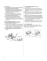
Page 6: ...y dangerous situation 3 Maintain the approach path so that the inclination angle of approach to the field is kept within 15 degrees 6 Loading Unloading to from a Truck Refer to P 27 1 When loading the...

Page 7: ...eat Reagent tank lid Reagent tank Hood Left boom Fuel tank Steps 2 Name of Each Part 1 External View 2 Driving Devices Hourmeter Manual pressure adjustment specification Differential lock pedal Brake...

Page 8: ...tion Steering wheel Auxiliary shift lever HST lever Glow lamp Water temperature warning lamp Charge lamp Oil pressure lamp Speedometer Pressure gauge Throttle lever Spray pump switch Key switch Fuse b...

Page 9: ...ecification Specification J Hydraulic Boom Up Down Open Close Specification Boom high low switch Right boom open close lever Left boom open close lever Right boom open close lever Left boom open close...

Page 10: ...peed km h Moving 0 to 10 Spraying 0 to 4 0 Brake also used as parking brake Wet multi disk mechanical type Tires front rear 120 90 26 4PR Air pressure 240 kPa Battery 60B24R Reagent tank capacity L 50...

Page 11: ...s Traveling speed km h Moving 0 to 10 Spraying 0 to 4 0 Brake also used as parking brake Wet multi disk mechanical type Tires front rear 120 90 26 4PR Air pressure 240 kPa Battery 60B24R Reagent tank...

Page 12: ...ing Constantly remove soiling and mud over the labels so that the information provided on them remains clearly visible Replace damaged warning labels with new ones If a part on which a warning label i...

Page 13: ...13 10 11 7 Part No 868146 8 Part No 689964 9 Part No 868145 10 Part No 689965 11 Part No 866073...

Page 14: ...12 13 14 Manual Boom Open Close Specification 14 Specification J 15 16 18 17 12 Part No 689967 13 Part No 689966 16 Part No 868147 18 Part No 869750 17 Part No 689969 15 Part No 864412 14 Part No 8681...

Page 15: ...ications J Q only 19 Manual Boom Open Close Specification 19 Hydraulic Boom Open Close Specification 19 Part No 868148 20 Part No 880324 CAUTION The lock pin will be in lock position If boom is not fu...

Page 16: ...n traveling on the machine use the accelerator pedal to adjust the engine speed Traveling Operation 1 HST Lever Tilt the lever forward from the N position to move forward or tilt it rearward to move i...

Page 17: ...position Also remember not to turn while the differential lock is actuated The machine may not turn in the intended direction Caution Be sure to cancel the differential lock before turning If the mac...

Page 18: ...p charge warning lamp This lamp turns on to warn when a charge system error is detected while the engine is turning Caution If this lamp turns on stop the engine and inspect the fan belt If the belt i...

Page 19: ...l or cooling water level is low check the fan belt tension and also check the radiator core and air cleaner for clogging If the lamp turns on frequently have the machine inspected by the Maruyama deal...

Page 20: ...ing to Pest Control Manual Pressure Adjustment Specification 1 Pressure Adjustment Dial Adjust the discharge pressure of the spray pump While monitoring the pressure gauge turn the pressure adjustment...

Page 21: ...3 Right Boom Open Close Lever Tilt the lever to the left and remove it from the cutout groove and then press it forward to open the right boom Pull the lever backward to close the right boom After th...

Page 22: ...orward to open the left boom or pull it toward you to close the left boom 3 Right Boom Open Close Lever Tilt the lever forward to open the right boom or pull it toward you to close the left boom The l...

Page 23: ...the knob bolts If the bolts are loose they may drop out during transport and cause accidents 2 Tires The wheelbase can be adjusted by reversing the tires or adding a spacer or spacers optional Cautio...

Page 24: ...immediately stop the engine and take an appropriate measure If you hear abnormal noise different from what you hear every day stop the engine and investigate the cause If the cause cannot be identifie...

Page 25: ...than the driver or objects Wear a helmet to ensure safety Exercise due caution and lower the speed when going through a narrow agricultural land or on a road with shoulders Trim weeds to expose the ro...

Page 26: ...Out 1 Get in out of the machine using the grip and steps 2 When getting out of the machine operate the boom high low switch or the lever in the case of the specification J to move each boom to the hi...

Page 27: ...R position pull the parking brake and apply chocks 3 Empty the reagent tank and drive forward to load the machine Move at a very low speed by tilting the HST lever forward slightly with the auxiliary...

Page 28: ...is kept within 15 degrees If the approach path to the field is soft or the inclination angle is 15 degrees or more be sure to use footboards to keep the inclination angle within 15 degrees If the len...

Page 29: ...ch to stop the spray pump and then remove the jet pump Warning Never feed water directly from a drinking water source or any lake or pond used for aquatic farming Reagent Preparation and Handling 1 Re...

Page 30: ...om Cone nozzle 1 4 Uncut nozzle N KA 8R For rice shower nozzle 25 13 pcs Center boom 7 pcs Right boom 13 pcs Total 33 pcs Optional sold separately Table of nozzle discharge flow rates per nozzle L min...

Page 31: ...osses through the nozzles etc The tire slip factor of the boom sprayer may vary depending on the conditions of the field in which case the diagrams must be corrected for the difference in slip factor...

Page 32: ...10a 75L 10a 100L 10a 125L 10a 150L 10a 175L 10a 200L 10a 1 6 1 7L min L min 13 16 18 21 23 26 29 31 34 36 39 42 44 B08 N KA 8R 47 1 Spray flow rate by nozzle L min Total discharge flow rate in L min 1...

Page 33: ...1 Specification J Spray flow rate by nozzle L min Total discharge flow rate in L min 2 3 4 Spray speed km h Nozzle pressure MPa Cone 1 4 Eco Shower B08 Kirinashi N KA 8R Must not be exceeded 1 3 L mi...

Page 34: ...to a desired level during spraying 5 Open the booms 1 Operate the boom high low switch or lever in the case of the specification J to move the booms to positions higher than the boom receivers 2 Opera...

Page 35: ...attery oils coolant etc on land into a river etc may be construed as a punishable violation of law Periodic Inspection Standards 1 The applicable inspection timing is indicated by 2 The timing of init...

Page 36: ...of joint and leakage of oil Mechanical devices Starting device Degree of pinion meshing Charge device Charge action Battery Fluid level 50 Fully charged 1 260 20 C Fully discharged 1 060 20 C Specific...

Page 37: ...eness and damage of mount Muffler function Machine frame and body Looseness and damage Location where abnormality was found during operation the day before Confirm that the applicable location is free...

Page 38: ...differential oil 1 0 L 6 Spray pump crank case SAE10W 30 API SJ grade or better 0 6 L 100 7 Spray pump cylinder base metal 3 to 5 drips Every 100 hours or every year 8 Each wire At start of work 9 Bra...

Page 39: ...39 Greasing locations Specifications J Brake pedal shaft Boom lift shaft 8 locations Boom rotational axis 3 locations each on left and right...

Page 40: ...f the parts directly with your hand Oil filter cartridge Replace every 200 hours or after 50 hours initially 1 The oil filter is of cartridge type so remove the entire case with a filter wrench and re...

Page 41: ...out from the screw tighten screw A 4 Next loosen screw B bleed air trapped between the fuel filter and solenoid pump in the same manner and tighten screw B 5 Turn the key switch to ON Operate the sole...

Page 42: ...the concentration of coolant according to the outside air temperature 10 C or above 30 10 to 25 C 40 2 Cleaning the inside of the radiator Open the drain plug and drain cooling water fully Thereafter...

Page 43: ...ging oil replace the filter also Type of oil Hydraulic oil wear resistant VG32 Amount of oil Approx 13 L When to change Initial change 50 hours Periodic change Every 200 hours 9 Inspecting the Spray P...

Page 44: ...the charge indicator vertically 2 If the charge indicator is clear or yellow gently tap the battery to remove air bubbles and then check again 3 Take an appropriate action according to the table below...

Page 45: ...w oil and operate the engine for around 5 minutes to spread oil to each part 8 Be sure to keep the throttle lever in the Low speed position 9 Fill up the fuel tank with fuel diesel oil 10 Store each b...

Page 46: ...the piping diagram indicates the flow direction of water or reagent The jet pump shown in the diagram is optional sold separately Boom nozzle Piping Diagram Feed valve Strainer Reagent tank Jet agitat...

Page 47: ...l filter and add new fuel Clogged fuel injection nozzle Contact the dealer where you purchased your machine from Clogged fuel filter Contact the dealer where you purchased your machine from Engine rel...

Page 48: ...your machine from Steering wheel related The steering wheel is heavy Insufficient tire pressure Adjust the pressure to the reference level Hydraulic device malfunction Contact the dealer where you pu...

Page 49: ...Quantity used Remarks Engine Air cleaner element 647156 1 Kubota 1G659 1122 0 Oil filter 642984 1 Kubota 15853 3246 0 V belt 577467 1 FM33 Fuel piping Filter assembly 196770 1 Kubota 1G313 43011 Eleme...

Page 50: ...50...

Page 51: ...51...

Page 52: ...52 P N 880041 00 Apr 2014...

Reviews: