11
5
Name and Function of Each Device
◼
Relating to Engine Operation
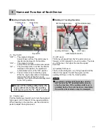
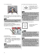
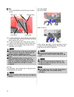
(1) Key Switch
“OFF” --- The engine is stopped.
Current does not flow. The ignition key is
inserted and removed in this position.
“ON” --- The engine is turning.
Current flows to each electrical component.
“GL” --- The glow lamp turns on. When the hand is
released in this position, the switch will
automatically return to the
“ON” position.
“ST” --- The cell motor turns to start the engine.
When the engine has started, immediately
release the hand. When the hand is
released, the switch will automatically return
to the
“ON” position.
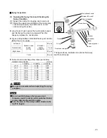
(2) Throttle Lever
Pull the throttle lever toward you to turn the engine at
high speed, or tilt it forward for low speed operation.
When traveling on the machine, use the accelerator
pedal to adjust the engine speed.
◼
Relating to Traveling Operation
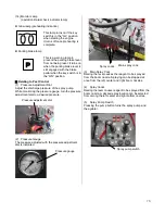
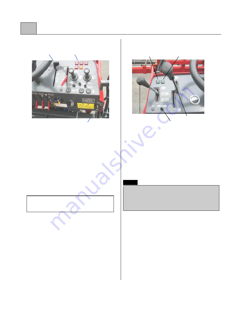
(1) HST Lever
Tilt the lever forward from the
“N” position to move
forward, or tilt it rearward to move in reverse. The more
you tilt the lever, the higher the machine speed
becomes.
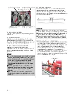
(2) Auxiliary Shift Lever
There are two shift gears: one for high speed and the
other for low speed. To start the engine, put the
auxiliary shift lever in the
“N – Start” position.
Caution
⚫
To perform auxiliary shift operation, put the
HST lever in the
“N” position and be sure to
stop the machine. If the auxiliary shift lever is
operated before the machine stops completely,
the auxiliary transmission may be damaged.
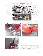
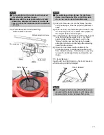
Glow lamp
Throttle lever
Key switch
⚫
Because of the starting safety device, the
engine will not start unless the auxiliary
shift lever is put in the “N – Start” position.
4WS indication lamp
Auxiliary shift lever
2WS indication lamp
HST lever
2-4WS selector switch


