background image

15

Water Hookup

PREPARE PLUMBING

The water valve uses a standard 1/4” (6.35 mm) 

compression fitting. 

Plumbing installation must observe all state and local 

codes. All water and drain connections MUST BE made by 

a licensed/qualified plumbing contractor. Failure to follow 

recommendations and instructions may result in damage 

and/or harm.

Water Supply Connection

When connecting the water supply, please note the 

following:

•  Before installing the unit and connecting to the cold 

water supply, review the local plumbing codes.

•  The water pressure should be between 20 and 120 psi 

(138 and 827 kPa).

• 

The water line MUST have a shut-off valve in the 

supply line.

•  The water line should be looped into 2 coils. This will 

allow the unit to be removed for cleaning and servicing. 

Make certain that the tubing is not pinched or damaged 

during installation.

Do not use any plastic water supply line. The line is under 

pressure at all times. Plastic may crack or rupture with age 

and cause damage to your home.Do not use tape or joint 

compound when attaching a braided flexible water supply 

line that includes a rubber gasket. The gasket provides 

an adequate seal – other materials could cause blockage 

of the valve.Failure to follow recommendations and 

instructions may result in damage and/or harm, flooding or 

void the product warranty.Use new hose set. Do not reuse 

old hose set.

INSTALLING THE WATER SUPPLY

!

WARNING

WARNING - 

Connect to potable water supply only.

•  Water Mineral Content:

•  TDS: greater than 5 ppm (mg/l) but less than 400 

ppm (mg/l)

•  Hardness: less than 200 mg/l (12 gpg)

•  Not recommended for use with softened water

!

CAUTION

!

CAUTION

Turn off water supply and disconnect electrical supply to 

unit prior to installation. Use caution when handling back 

panel. The edges could be sharp.

1. 

Turn off water supply and disconnect electrical supply 

to product prior to attempting installation.

2.  Remove the back panel.

3.  Thread water line through back panel hole (with 

bushing).

4.  Locate water valve inlet and connect to valve.

5.  Turn on water supply and check for leaks.

6.  Reinstall back panel.

!

CAUTION

Figure 37

4

Figure 38

Summary of Contents for MLNP115-SS01B

Page 1: ...RTED QUICK REFERENCE GUIDE MARVEL UNDERCOUNTER REFRIGERATION T H E O R I G I N A L R E F R I G E R AT I O N E X P E RT S S I N C E 1 8 9 2 M L N P 1 1 5 I G 0 1 A M L N P 1 1 5 S S 0 1 B M S N P 1 1 5...

Page 2: ...d Labels CAUTION Hazards or unsafe practices which could re sult in personal injury or property product damage NOTE Important information to help assure a problem free installation and operation CONTE...

Page 3: ...required when registering your appliance Service Number Serial Number Date of Purchase Dealer s name and address The service number and serial number can be found on the serial plate which is located...

Page 4: ...age and loss of cooling capacity For this reason it is important this area to not be obstructed and the grille openings kept clean Marvel does not recommend the use of a custom made grille as air flow...

Page 5: ...shut down GFCI s are generally not used on circuits with power equip ment that must run unattended for long periods of time un less required to meet local building codes and ordinances Electrical Con...

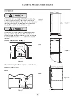
Page 6: ...o alter the wall just behind the drain connection on the unit to accommodate the drain CUTOUT DIMENSIONS MSNP115 15 cutout width may be sufficient if opening is exact and square PRODUCT DIMENSIONS REA...

Page 7: ...in an adjacent cabinet 24 610 mm 5 8 16 mm Figure 11 2 51 mm 4 102 mm Water Line Drain 7 191 mm 3 1 8 80 mm 4 102 mm 7 191 mm Power Cord 6 ft 183 cm Figure 12 FRONT TOP SIDE 14 15 16 379 mm 3 89 mm 28...

Page 8: ...l To install hinge cover Press hinge cover squarely over hinge Door Alignment and Adjustment Align and adjust the door if it is not level or is not sealing properly If the door is not sealed the unit...

Page 9: ...ENTS To align and adjust the door MSNP115 1 Gently pry off hinge cover from top of unit 2 Loosen do not remove top and bottom hinge screws using a Torx T 25 screwdriver 3 Align door squarely with cabi...

Page 10: ...und the door no gaps Carefully examine the door s gasket to ensure that it is firmly in contact with the cabinet Also make sure the door gasket is not pinched on the hinge side of the door Do not atte...

Page 11: ...hinge with the outer edge of the unit 4 Tighten three hinge screws Figure 25 NOTE REVERSING THE DOOR 1 Open door 2 Using T 25 Torx bit loosen screw 1 and remove screw 2 on top and bottom hinge Slide a...

Page 12: ...g s rear height Shorten the unit height in the front by adjusting the front legs This allows the unit to be gently tipped into the opening Readjust the front legs to level the unit after it is correct...

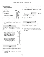
Page 13: ...h upon removal 7 Using a 7 64 3 mm drill bit drill 6 pilot holes into the wood panel 1 2 12 mm deep using the holes in the door frame as a guide It is important to ensure that all drilled holes are dr...

Page 14: ...ipe Disposal Assembly Y Branch Tail Piece INSTALLING THE DRAIN PLUMBING CAUTION NOTE Cold Water Hot Water Waste Waste Shut O Valve Figure 34 Air Gap Optional Hook Up Cold Water Hot Water Waste Shut O...

Page 15: ...e with age and cause damage to your home Do not use tape or joint compound when attaching a braided flexible water supply line that includes a rubber gasket The gasket provides an adequate seal other...

Page 16: ...f product loaded door openings etc Marvel recommends allowing the unit to reach set points before loading NOTE Ice The Nugget Ice Machine produces cylindrical bits of compressed ice approximately 3 4...

Page 17: ...eaning section Showroom Mode Hold and for 5 seconds The oF oC symbol will flash Display will be lit and interior light with function Unit will not cool Repeat command to return to normal operation DOO...

Page 18: ...teel and complete removal of the rust may not be possible INTERIOR CLEANING Disconnect power to the unit Clean the interior and all removed components using a mild nonabrasive detergent and warm solut...

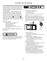
Page 19: ...conds a will appear in the display b Remove access shield c Remove all ice in bin d Remove any ice protruding from the ice dispenser tube 2 Insert the end of the cleaning tube into the ice dispenser s...

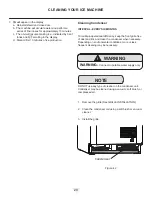
Page 20: ...L EVERY SIX MONTHS To maintain operational efficiency keep the front grille free of dust and lint and clean the condenser when necessary Depending on environmental conditions more or less frequent cle...

Page 21: ...t remain open to prevent formation of mold and mildew Open door a minimum of 2 50 mm to provide the necessary ventilation WINTERIZATION If the unit will be exposed to temperatures of 40oF 5oC or less...

Page 22: ...r area A listing of authorized service centers is also available at www marvelrefrigeration com under the service and support section In all correspondence regarding service be sure to give the servic...

Page 23: ...igence accident or improper use maintenance instal lation service repair acts of God fire flood or other natural disasters The product must be installed operated and maintained in accordance with the...

Page 24: ...hange without notice Such revisions do not entitle the buyer to corresponding changes improvements additions replacements or compensation for previously purchased products www marvelrefrigeration com...

Reviews: