237
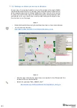
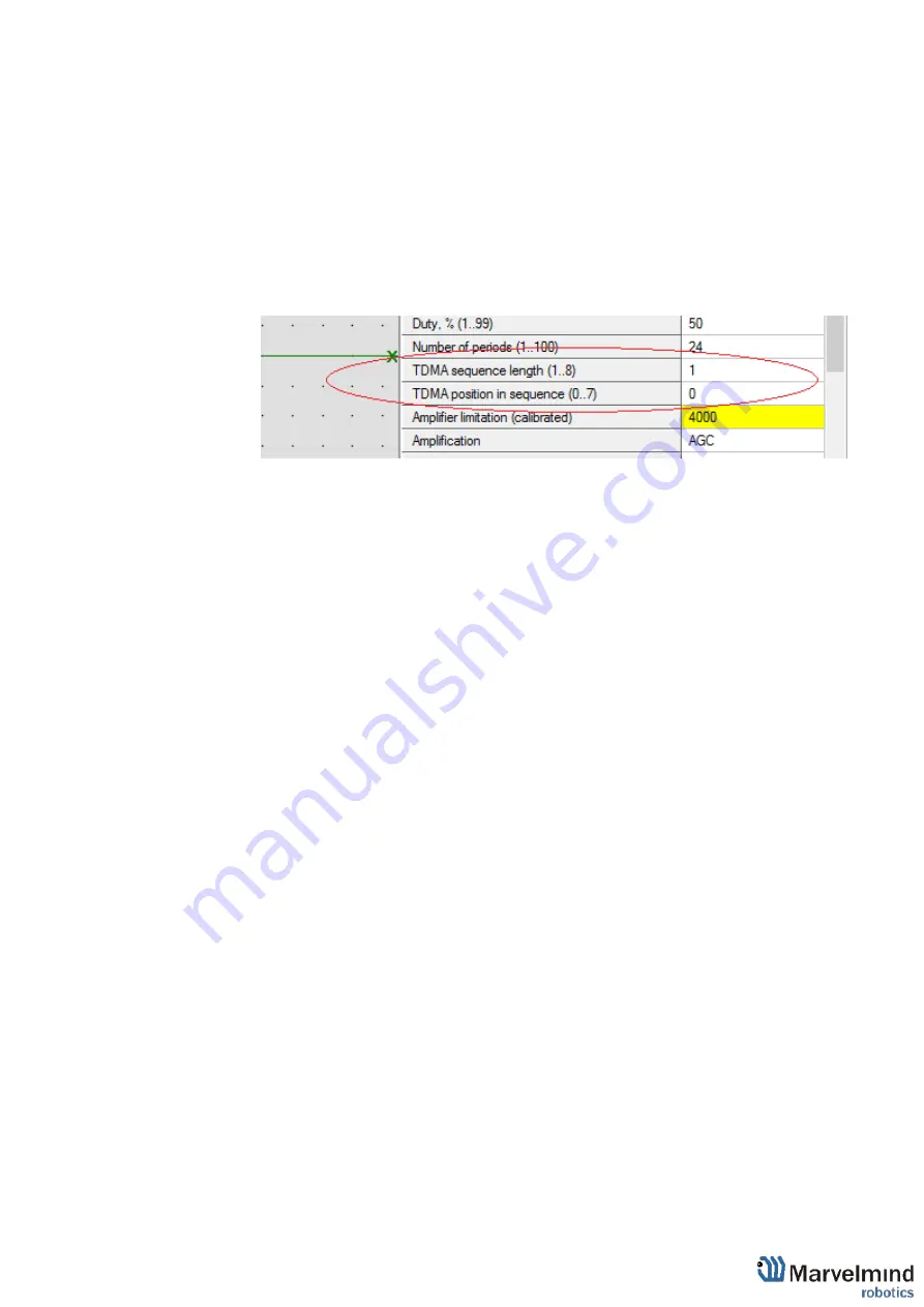
11.3.7. If submaps with the same set of frequencies intersect, it is necessary to
use TDMA.
(This is the mode of sequential radiation, when for each
stationary beacon the number of the cycle in which it should emit and the
number of cycles of radiation after which these numbers are repeated is set)
For example, in the room there are beacons 19kHz, 45kHz and two 31kHz
and submaps respectively 19kHz+31kHz and 31kHz+45kHz both include
beacon 31kHz, therefore for all beacons the length of the TDMA sequence is
set to 2, while the position in the TDMA sequence for beacons in
19kHz+31kHz submap is set to 0, and for beacons in 31kHz+45kHz submap
is set to 1. As a result, the radiation of beacons in submaps occurs
sequentially, first 19kHz+31kHz submap, then 31kHz+45kHz submap. You
can also use absolutely the same set of frequencies in submaps (Submap0 =
19kHz+31kHz, Submap1 = 19KHz+31KHz)
11.3.8. Activate mobile beacons.
11.3.9. Freeze the entire map. Now, you can work with it.
11.3.10. If you have any jumps, that can mean that you ha
ve wrong submaps’
positions. Unfreeze all and try to move it until you get their correct positions.
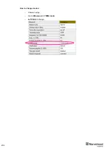
TDMA modes:
System supports two modes of TDMA:
-
Mode 1 (Adaptive)
: Hedge determines which submap sees it better at the
moment, and tracks in it. It can give better tracking, but in bad conditions, it
may cause mistracking
-
Mode 2 (Classic)
: Hedge tracks in two submaps one by one. It can give solid
50/50 tracking in conditions where one submap can’t see the hedge at all. After
measurements, Real-Time Player makes tracking smooth, filtering out
mistracking
Each mode has its pros and cons. Try them both and choose the best suiting for
your case.
Summary of Contents for IA-04-2D-Badge
Page 1: ...Marvelmind Indoor Navigation System Operating manual v2022_08_24 www marvelmind com ...
Page 21: ...21 Beacon Mini TX Beacon Industrial RX Beacon Industrial TX Metal ...
Page 22: ...22 Industrial Super Beacon Plastic ...
Page 39: ...39 Figure 7 One External Microphone connection Figure 8 Two External Microphone connection ...
Page 44: ...44 Figure 3 One external microphone soldering Figure 4 Two external microphones soldering ...
Page 46: ...46 Figure 7 Two External Microphones final view Figure 8 Two External Microphones final view ...
Page 118: ...118 6 6 28 The system is now fully operational ...
Page 180: ...180 Floor 5 is enabled Floor 4 is enabled ...
Page 190: ...190 Z X ...
Page 207: ...207 Choose color and press OK Color applied Now background matches floorplan ...
Page 214: ...214 9 24 IMU axis positioning Super Beacon IMU axis positions HW v4 9 IMU axis positions ...
Page 215: ...215 Mini TX IMU axis positions Mini RX beacon IMU axis positions ...
Page 219: ...219 Real time player turned on ...
Page 223: ...223 10 2 Beacon HW v4 9 external interface 4x4 pinout top view ...
Page 224: ...224 10 3 Modem HW v4 9 external interface pinout top view ...
Page 232: ...232 If everything done correctly Own IP address will change Static IP settings completed ...
Page 238: ...238 How to change modes Choose hedge Go to Ultrasound TDMA mode Left Click to change ...


