40
3.6.2.
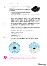
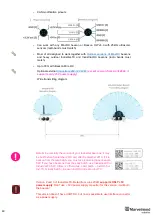
Beacon Mini-RX
The Beacon Mini-RX can be used in both the Non-Inverse
Architecture (NIA) and in the Inverse Architecture (IA):
The Mini-RX beacon HW differs from the regular Beacon HW
v4.9 in several ways:
-
It is an RX-only beacon, i.e. it can receive, but it cannot
transmit ultrasonic signal
-
The fact that it is RX-only makes it far more sensitive, i.e. you will get a longer range
between Beacon HW 4.9 and Mini-RX than between Beacon HW 4.9 and Beacon
HW 4.9.
-
Mini-RX beacon can receive any ultrasonic frequency from the bands: 19kHz,
22kHz, 25kHz, 28kHz, 31kHz, 34kHz, 37kHz, 45kHz. The filter can be simply
selected in the Dashboard. At the same time, the working ultrasonic frequency of
Beacon HW v4.9 is HW-
defined by ultrasonic sensors and can’t be changed
-
Mini-RX beacon can receive several ultrasonic frequencies at once. That is used in
Inverse Architecture. See the comparison:
-
The Mini-RX Beacon is significantly smaller than Super-Beacon
-
Can play a role of stationary beacon when imputing coordinates manually (in NIA)
-
Can play a role of mobile beacon (in IA system)
-
Has digital microphone, which is more sensitive than regular sensors
-
Supports 868/915MHz radio only
-
Light weighted
-
Can be
-
The component of the
-
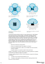
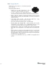
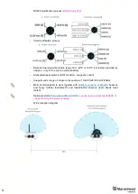
It has 360° reception angle (horizontally) and 180° reception angle (vertically)
Reception diagram. Digital microphone has about 360° (horizontally) and 180°
(vertically) reception angle
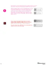
Mini-RX beacon may be over discharged. In that case do the following:
Turn off the beacon with DIP switches and charge it for 1 hour. Then turn the
beacon on, flash the latest SW via DFU Programming and charge it for 1 hour
again
Summary of Contents for IA-04-2D-Badge
Page 1: ...Marvelmind Indoor Navigation System Operating manual v2022_08_24 www marvelmind com ...
Page 21: ...21 Beacon Mini TX Beacon Industrial RX Beacon Industrial TX Metal ...
Page 22: ...22 Industrial Super Beacon Plastic ...
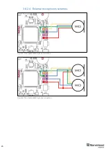
Page 39: ...39 Figure 7 One External Microphone connection Figure 8 Two External Microphone connection ...
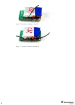
Page 44: ...44 Figure 3 One external microphone soldering Figure 4 Two external microphones soldering ...
Page 46: ...46 Figure 7 Two External Microphones final view Figure 8 Two External Microphones final view ...
Page 118: ...118 6 6 28 The system is now fully operational ...
Page 180: ...180 Floor 5 is enabled Floor 4 is enabled ...
Page 190: ...190 Z X ...
Page 207: ...207 Choose color and press OK Color applied Now background matches floorplan ...
Page 214: ...214 9 24 IMU axis positioning Super Beacon IMU axis positions HW v4 9 IMU axis positions ...
Page 215: ...215 Mini TX IMU axis positions Mini RX beacon IMU axis positions ...
Page 219: ...219 Real time player turned on ...
Page 223: ...223 10 2 Beacon HW v4 9 external interface 4x4 pinout top view ...
Page 224: ...224 10 3 Modem HW v4 9 external interface pinout top view ...
Page 232: ...232 If everything done correctly Own IP address will change Static IP settings completed ...
Page 238: ...238 How to change modes Choose hedge Go to Ultrasound TDMA mode Left Click to change ...


