56
4.
Software pack
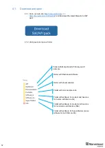
In this chapter you can find out how to use our
Always remember:
-
All devices must be flashed from the same SW Pack
-
Don’t look on the dates in the name of file, they can be different, pay attention
only to the name of the device.
-
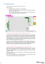
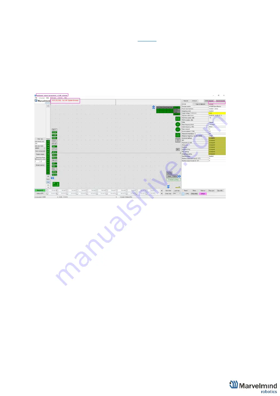
If the device was flashed with an older firmware version then Dashboard, this
will be displayed in the diagnostic message window:
Changes in files in the Marvelmind SW pack (from SW version 7.200):
The SW files for beacons/modems that don’t require an update with the new release
won’t be replaced with the new files in the new SW pack. However, the Dashboard will
assign the new version number to them based on the newly introduced a SW version
compatibility table. Thus, the files physically remain the same, but, if they are compatible
with the latest SW pack, the Dashboard will automatically substitute their older SW
version number with the latest SW version number
It is done in order to detect and avoid the most common mistake by the users
– an
attempt to run incompatible SW versions of beacons, modem, Dashboard obtained from
different SW packs, i.e. not updating the beacons/modems to the latest SW version from
the same SW pack upon getting the equipment from Marvelmind Robotics
Changes in naming of SW versions and licenses (from SW version 7.200):
Optional SW feature brought by MMSW0005 are now marked with L at the end of the
release name. For example, v7.200
– only base SW features are enabled – by default.
Purchasing the MMSW0005 license activates optional features and the SW version
changes to v7.200L
Naming example IA vs. NIA: v7.200 and v7.200L
– SW for NIA and MF NIA, v7.200i
and v7.200Li
– SW for IA
If some beacons/modems don’t have the MMSW0005 license, their addresses are listed
in the upper part of the Dashboard
– information window
Summary of Contents for IA-04-2D-Badge
Page 1: ...Marvelmind Indoor Navigation System Operating manual v2022_08_24 www marvelmind com ...
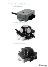
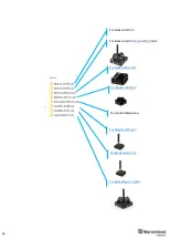
Page 21: ...21 Beacon Mini TX Beacon Industrial RX Beacon Industrial TX Metal ...
Page 22: ...22 Industrial Super Beacon Plastic ...
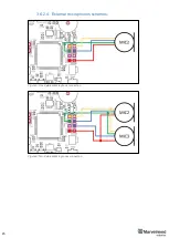
Page 39: ...39 Figure 7 One External Microphone connection Figure 8 Two External Microphone connection ...
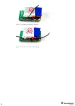
Page 44: ...44 Figure 3 One external microphone soldering Figure 4 Two external microphones soldering ...
Page 46: ...46 Figure 7 Two External Microphones final view Figure 8 Two External Microphones final view ...
Page 118: ...118 6 6 28 The system is now fully operational ...
Page 180: ...180 Floor 5 is enabled Floor 4 is enabled ...
Page 190: ...190 Z X ...
Page 207: ...207 Choose color and press OK Color applied Now background matches floorplan ...
Page 214: ...214 9 24 IMU axis positioning Super Beacon IMU axis positions HW v4 9 IMU axis positions ...
Page 215: ...215 Mini TX IMU axis positions Mini RX beacon IMU axis positions ...
Page 219: ...219 Real time player turned on ...
Page 223: ...223 10 2 Beacon HW v4 9 external interface 4x4 pinout top view ...
Page 224: ...224 10 3 Modem HW v4 9 external interface pinout top view ...
Page 232: ...232 If everything done correctly Own IP address will change Static IP settings completed ...
Page 238: ...238 How to change modes Choose hedge Go to Ultrasound TDMA mode Left Click to change ...

