88
GTXI User's Guide
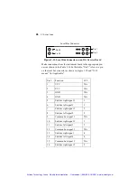
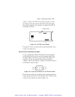
Pin 1
Local Bus Connector
Pin 2
Pin 39
Pin 40
Figure 3-13: Local Bus Connector on an ISA Carrier Board
Make connections from the instrument board to the appropriate pin-
outs as shown in the Table 3-14. In this table, “Pin #” refers to a pin
on the local bus connector as shown in Figure 3-10 and “N/A”
means “Not Applicable.”
Pin #
Function
JP #
1 VCC
N/A
2 VCC
N/A
3 GND
N/A
4 GND
N/A
5
Sub-bus right signal 1
1
6
Sub-bus left signal 1
1
7
Sub-bus right signal 2
2
8
Sub-bus left signal 2
2
9
Common bus signal 1
N/A
10
Sub-bus right signal 3
3
11
Sub-bus left signal 3
3
12
Common bus signal 2
N/A
13
Sub-bus right signal
4
14
Sub-bus left signal 4
4
15
Common bus signal 3
N/A
16
Sub-bus right signal 5
5
Artisan Technology Group - Quality Instrumentation ... Guaranteed | (888) 88-SOURCE | www.artisantg.com


