90
GTXI User's Guide
Common Bus
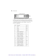
The signals in the center of J4 (the ‘B’ signals in Figure 3-9 above)
are connected to a common bus. When an instrument board is
connected to the common bus for a particular signal (Figure 3-4), its
signal will connect to all other instruments also connected to the
common bus for that same signal, regardless of the slot number they
are placed in.
To use the common bus, place a connection from the instrument
board to the appropriate local bus connector pin. For example, to
use the common bus for signal 2, Table 3-14 says to place a
connection from the instrument board to Pin 12 on the local bus
connector.
For example, when a board is placed in the platform in slot 6, the
signal for slot 6-B-2 is automatically connected to the B-2 signals
for any other boards also connected to the common bus for that
signal.
Connecting Adjacent Boards via a Sub-bus
Most users prefer to place the two instrument boards that need to be
connected adjacent to each other on the GTXI platform and use a
sub-bus. The sub-bus works by connecting to the left and right
signals of adjacent boards.
For example, the signal in slot 6-C-9 is connected by a sub-bus to
the signal in slot 5-A-9. Using that example, to connect the board in
slot 6 to the signal in slot 5-A-9, do the following:
1. Determine which pin on the local bus connector in slot 6 to use
by looking in Table 3-14. Since slot 5 is to the left of slot 6, use
“sub-bus left.” Since the target signal is to be 9, use “sub-bus
left signal 9.” In Table 3-14, that means Pin 29 on the local bus
connector for slot 6.
2. Connect the instrument board on the carrier board in slot 6 to
the Pin 29 on the local bus connector of the carrier board.
Artisan Technology Group - Quality Instrumentation ... Guaranteed | (888) 88-SOURCE | www.artisantg.com


