40
GTXI User's Guide
Up to four GTXI-701-PCT boards may be installed in a host
PC to control up to four GTXI platforms. Each must be set to a
different base address that is determined by SEL0 and SEL1.
The SEL0 and SEL1 switch settings for a given GTXI-701-
PCT boards depend on whether it is the first, second, third, or
fourth such GTXI-701-PCT board used in a host PC.
Note
: The default settings are recommended if only one
GTXI-701-PCT is installed.
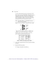
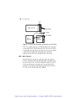
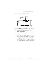
Figure 2-14 shows an example of a single DIP switch setting:
On
Off
The switch
is pushed
up.
The switch
is pushed
down.
Figure 2-14: ON and OFF positions for a DIP switch
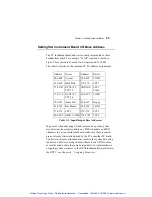
The DIP switch settings and base addresses for the four
possible boards are listed in the following table:
Board
Base
Address SEL1 SEL0
1st 178-17B On
On
2nd 17C-17F Off On
3rd
57C-57F
On
Off
4th
578-57B
Off
Off
Table 2-1: DIP switch settings for four boards
3. In the host PC, install the GTXI-701-PCT board in an available
16-bit slot.
4. Mount the GTXI unit by either:
♦
Placing it on a regular work surface, or
Artisan Technology Group - Quality Instrumentation ... Guaranteed | (888) 88-SOURCE | www.artisantg.com


