Chapter 2 - Installing and Operating
49
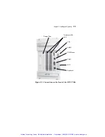
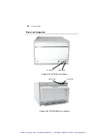
The front panel of the GTXI contains two power switches, Main
and Auxiliary, to control the separate DC power supplies.
On the GT7700, the green Main switch controls the embedded
controller and the PCI slots, and the blue Auxiliary switch controls
the ISA slots.
On the GTXI-700, the green Main switch controls instrument slot
13 and the blue Auxiliary switch controls slots 0-12. When the
GTXI-700 contains a GTPC-7586 controller module, these devices
are installed in slot 13 and are controlled by the Main switch.
(Because of its size, the GTPC-7586 controller module occupies
slots 10-13.)
Power-on Sequence in standalone Mode
Turn on the power to the GTXI platform by pressing the Main and
Auxiliary switches at the same time and waiting for the boot
sequence to complete.
Note
:
Some PC-based instruments require their drivers be loaded
by the CONFIG.SYS file. This is the reason the controller is
turned on at the same time as the instrumentation.
Power-on Sequence for GTXI-700 in Bus Extender Mode
1. Turn on the GTXI-700 platform Main and Auxiliary switches.
2. Turn on the host computer and wait for the boot sequence to
complete.
Suspending Operation of the Instrument Platform
In both stand-alone and bus extender modes, the instrument
platform can be suspended by turning off the auxiliary power
supply while the controller is running. This enables new boards to
be installed, or existing board configuration parameters and settings
to be changed, without having to reboot the computer and load the
Artisan Technology Group - Quality Instrumentation ... Guaranteed | (888) 88-SOURCE | www.artisantg.com

